Difference between revisions of "Template:FMB2 First start card"
From Wiki Knowledge Base | Teltonika GPS
Simkunas.ma (talk | contribs) (Created page with "centre <b><font size="+10">{{{model|FMB2YX}}} Small and professional waterproof tracker with internal high gain {{{antenna|GNSS/GSM antenna...") |
|||
| (76 intermediate revisions by 6 users not shown) | |||
| Line 1: | Line 1: | ||
[[Image:Qsg_rut950_teltonika.PNG|centre]] | [[Image:Qsg_rut950_teltonika.PNG|centre]] | ||
| − | |||
| − | < | + | <b>{{{model|FMB20X}}} Small and professional waterproof tracker with high gain {{{GPS_antenna|internal}}} {{{antenna|GNSS/GSM antennas}}}, Bluetooth and high capacity internal {{{battery|Ni-MH}}} battery</b>{{{pic|[[Image:FMB202.png|400px|right]]}}} |
| + | __TOC__ | ||
| + | =='''How to insert Micro-SIM card'''== | ||
| + | # '''Unscrew''' 6 screws counter-clockwise that are located on the '''bottom''' of the device. | ||
| + | # Remove the '''cover'''. | ||
| + | # Insert '''Micro-SIM''' card as shown with '''PIN request disabled''' or read '''{{{sim_pin|[[FMB204 Security info|Security info]]}}}''' how to enter it later in '''Configurator'''. Make sure that Micro-SIM card '''cut-off corner''' is pointing forward to slot. | ||
| + | # Connect battery as shown to device. | ||
| + | # After configuration, attach device '''cover''' and put the '''screws''' back in. | ||
| + | # Device is ready to be connected. | ||
| + | [[Image:case7.png|250px]][[Image:case4.png|250px]][[Image:case2.png|250px]] <br> | ||
| + | [[Image:case5.png|250px]][[Image:case3.png|250px]][[Image:case6.png|250px]] | ||
| + | {| | ||
| + | |- | ||
| + | | [[File:Alert.png|left|link=]] || <b>{{{sim_type|Micro-}}}SIM card insertion/removal must be performed when device is powered off – external voltage and battery are disconnected. Otherwise {{{sim_type|Micro-}}}SIM card might be damaged or device will not detect it.</b> | ||
| + | |} | ||
| − | + | =='''Cable colors'''== | |
| − | + | {| class="wikitable" | |
| − | + | |+ | |
| − | + | ! style="width:10%; border: 1px solid white; border-bottom: 2px solid #0054A6; background: white; color: #0054A6; text-align: left;"| PIN NUMBER | |
| − | + | ! style="width:15%; border: 1px solid white; border-bottom: 2px solid #0054A6; background: white; color: #0054A6; text-align: left;"| PIN NAME | |
| − | + | ! style="width:25%; border: 1px solid white; border-bottom: 2px solid #0054A6; background: white; color: #0054A6; text-align: left;"| DESCRIPTION | |
| − | + | | style="border: 1px solid white; border-bottom: 2px solid #E8E8E8; text-align: left; vertical-align: center; background: white;" rowspan="13" | [[Image:204_connector.png|240px|center]] | |
| − | + | |- | |
| − | + | | style="border: 1px solid white; border-bottom: 2px solid #E8E8E8; text-align: left; vertical-align: center; background: white;"| <span style=color:#000000>'''Red'''</span> | |
| − | + | | style="border: 1px solid white; border-bottom: 2px solid #E8E8E8; text-align: left; vertical-align: center; background: white;"| VCC (6-30)V DC (+) | |
| − | + | | style="border: 1px solid white; border-bottom: 2px solid #E8E8E8; text-align: left; vertical-align: center; background: white;"| Power supply (+6...30 V DC). | |
| − | + | |- | |
| − | + | | style="border: 1px solid white; border-bottom: 2px solid #E8E8E8; text-align: left; vertical-align: center; background: white;"| <span style=color:#000000>'''Black'''</span> | |
| − | + | | style="border: 1px solid white; border-bottom: 2px solid #E8E8E8; text-align: left; vertical-align: center; background: white;"| GND (-) | |
| − | + | | style="border: 1px solid white; border-bottom: 2px solid #E8E8E8; text-align: left; vertical-align: center; background: white;"| Ground. | |
| − | + | |- | |
| − | + | | style="border: 1px solid white; border-bottom: 2px solid #E8E8E8; text-align: left; vertical-align: center; background: white;"| <span style=color:#000000>'''Yellow'''</span> | |
| − | + | | style="border: 1px solid white; border-bottom: 2px solid #E8E8E8; text-align: left; vertical-align: center; background: white;"| DIN 1 | |
| − | + | | style="border: 1px solid white; border-bottom: 2px solid #E8E8E8; text-align: left; vertical-align: center; background: white;"| Digital input, channel 1. | |
| − | + | |- | |
| − | + | | style="border: 1px solid white; border-bottom: 2px solid #E8E8E8; text-align: left; vertical-align: center; background: white;"| <span style=color:#000000>'''White/Green'''</span> | |
| − | + | | style="border: 1px solid white; border-bottom: 2px solid #E8E8E8; text-align: left; vertical-align: center; background: white;"| DIN 2 | |
| − | + | | style="border: 1px solid white; border-bottom: 2px solid #E8E8E8; text-align: left; vertical-align: center; background: white;"| Digital input, channel 2. | |
| − | + | |- | |
| − | + | | style="border: 1px solid white; border-bottom: 2px solid #E8E8E8; text-align: left; vertical-align: center; background: white;"| <span style=color:#000000>'''White'''</span> | |
| − | + | | style="border: 1px solid white; border-bottom: 2px solid #E8E8E8; text-align: left; vertical-align: center; background: white;"| DIN 3 | |
| − | + | | style="border: 1px solid white; border-bottom: 2px solid #E8E8E8; text-align: left; vertical-align: center; background: white;"| Digital input, channel 3. | |
| − | + | |- | |
| − | + | | style="border: 1px solid white; border-bottom: 2px solid #E8E8E8; text-align: left; vertical-align: center; background: white;"| <span style=color:#000000>'''Grey'''</span> | |
| − | + | | style="border: 1px solid white; border-bottom: 2px solid #E8E8E8; text-align: left; vertical-align: center; background: white;"| AIN 1 | |
| − | + | | style="border: 1px solid white; border-bottom: 2px solid #E8E8E8; text-align: left; vertical-align: center; background: white;"| Analog input, channel 1. Input range: 0-30 V DC. | |
| − | + | |- | |
| − | + | | style="border: 1px solid white; border-bottom: 2px solid #E8E8E8; text-align: left; vertical-align: center; background: white;"| <span style=color:#000000>'''White/Orange'''</span> | |
| − | + | | style="border: 1px solid white; border-bottom: 2px solid #E8E8E8; text-align: left; vertical-align: center; background: white;"| DOUT 1 | |
| − | + | | style="border: 1px solid white; border-bottom: 2px solid #E8E8E8; text-align: left; vertical-align: center; background: white;"| Digital output, channel 1. Open collector output. Max. 3,3 A DC. | |
| − | + | |- | |
| − | + | | style="border: 1px solid white; border-bottom: 2px solid #E8E8E8; text-align: left; vertical-align: center; background: white;"| <span style=color:#000000>'''Violet'''</span> | |
| − | + | | style="border: 1px solid white; border-bottom: 2px solid #E8E8E8; text-align: left; vertical-align: center; background: white;"| DOUT 2 | |
| − | + | | style="border: 1px solid white; border-bottom: 2px solid #E8E8E8; text-align: left; vertical-align: center; background: white;"| Digital output, channel 2. Open collector output. Max. 3,3 A DC. | |
| − | + | |-FFA500 | |
| − | + | | style="border: 1px solid white; border-bottom: 2px solid #E8E8E8; text-align: left; vertical-align: center; background: white;"| <span style=color:#000000>'''Green'''</span> | |
| + | | style="border: 1px solid white; border-bottom: 2px solid #E8E8E8; text-align: left; vertical-align: center; background: white;"| 1WIRE DATA | ||
| + | | style="border: 1px solid white; border-bottom: 2px solid #E8E8E8; text-align: left; vertical-align: center; background: white;"| Data channel for 1–Wire devices. | ||
| + | |- | ||
| + | | style="border: 1px solid white; border-bottom: 2px solid #E8E8E8; text-align: left; vertical-align: center; background: white;"| <span style=color:#000000>'''Blue'''</span> | ||
| + | | style="border: 1px solid white; border-bottom: 2px solid #E8E8E8; text-align: left; vertical-align: center; background: white;"| 1WIRE POWER | ||
| + | | style="border: 1px solid white; border-bottom: 2px solid #E8E8E8; text-align: left; vertical-align: center; background: white;"| +3,8 V output for 1–Wire devices. | ||
| + | |- | ||
| + | |} | ||
Latest revision as of 17:03, 15 January 2020
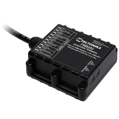
FMB20X Small and professional waterproof tracker with high gain internal GNSS/GSM antennas, Bluetooth and high capacity internal Ni-MH battery
How to insert Micro-SIM card
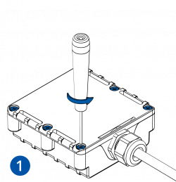
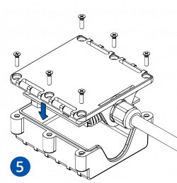
- Unscrew 6 screws counter-clockwise that are located on the bottom of the device.
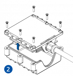
- Remove the cover.
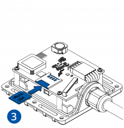
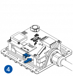
- Insert Micro-SIM card as shown with PIN request disabled or read Security info how to enter it later in Configurator. Make sure that Micro-SIM card cut-off corner is pointing forward to slot.
- Connect battery as shown to device.
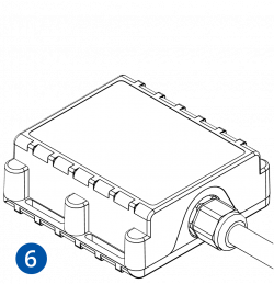
- After configuration, attach device cover and put the screws back in.
- Device is ready to be connected.
 |
Micro-SIM card insertion/removal must be performed when device is powered off – external voltage and battery are disconnected. Otherwise Micro-SIM card might be damaged or device will not detect it. |
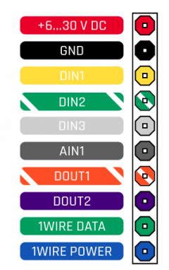
Cable colors
| PIN NUMBER | PIN NAME | DESCRIPTION | |
|---|---|---|---|
| Red | VCC (6-30)V DC (+) | Power supply (+6...30 V DC). | |
| Black | GND (-) | Ground. | |
| Yellow | DIN 1 | Digital input, channel 1. | |
| White/Green | DIN 2 | Digital input, channel 2. | |
| White | DIN 3 | Digital input, channel 3. | |
| Grey | AIN 1 | Analog input, channel 1. Input range: 0-30 V DC. | |
| White/Orange | DOUT 1 | Digital output, channel 1. Open collector output. Max. 3,3 A DC. | |
| Violet | DOUT 2 | Digital output, channel 2. Open collector output. Max. 3,3 A DC. | |
| Green | 1WIRE DATA | Data channel for 1–Wire devices. | |
| Blue | 1WIRE POWER | +3,8 V output for 1–Wire devices. |

