1-Wire Temperature Sensors: Difference between revisions
No edit summary |
|||
| (3 intermediate revisions by 2 users not shown) | |||
| Line 24: | Line 24: | ||
==Product Specification== | ==Product Specification== | ||
{| class="wikitable" | |||
|+ | |||
! style="width:30%; border: 1px solid white; border-bottom: 2px solid #0054A6; background: white; color: #0054A6; text-align: left;" |NAME | |||
! style="border: 1px solid white; border-bottom: 2px solid #0054A6; background: white; color: #0054A6; text-align: left;" |DESCRIPTION | |||
|- | |||
| style="border: 1px solid white; border-bottom: 2px solid #E8E8E8; text-align: left; vertical-align: center; background: white;" |Interface | |||
| style="border: 1px solid white; border-bottom: 2px solid #E8E8E8; text-align: left; vertical-align: center; background: white;" |1-Wire Interface | |||
|- | |||
| style="border: 1px solid white; border-bottom: 2px solid #E8E8E8; text-align: left; vertical-align: center; background: white;" |Wiring | |||
| style="border: 1px solid white; border-bottom: 2px solid #E8E8E8; text-align: left; vertical-align: center; background: white;" |<span style="color:#D8D800"><b>Yellow</b></span> wire – 1-wire data, <span style="color:red"><b>Red</b></span> wire - 1-wire Power, <b>Black</b> wire - ground. | |||
|- | |||
| style="border: 1px solid white; border-bottom: 2px solid #E8E8E8; text-align: left; vertical-align: center; background: white;" |Power Supply | |||
| style="border: 1px solid white; border-bottom: 2px solid #E8E8E8; text-align: left; vertical-align: center; background: white;" | 3V - 5,5V. Can be Powered from Data Line (parasitic connection) | |||
|- | |||
| style="border: 1px solid white; border-bottom: 2px solid #E8E8E8; text-align: left; vertical-align: center; background: white;" |Accuracy | |||
| style="border: 1px solid white; border-bottom: 2px solid #E8E8E8; text-align: left; vertical-align: center; background: white;" |±0.5°C (-10°C to +85°C) | |||
|- | |||
| style="border: 1px solid white; border-bottom: 2px solid #E8E8E8; text-align: left; vertical-align: center; background: white;" |Temperature range | |||
| style="border: 1px solid white; border-bottom: 2px solid #E8E8E8; text-align: left; vertical-align: center; background: white;" |-55°C to 125°C (-67°F to +257°F) | |||
|- | |||
| style="border: 1px solid white; border-bottom: 2px solid #E8E8E8; text-align: left; vertical-align: center; background: white;" |Cable length | |||
| style="border: 1px solid white; border-bottom: 2px solid #E8E8E8; text-align: left; vertical-align: center; background: white;" |8 meters | |||
|- | |||
| style="border: 1px solid white; border-bottom: 2px solid #E8E8E8; text-align: left; vertical-align: center; background: white;" |Tube | |||
| style="border: 1px solid white; border-bottom: 2px solid #E8E8E8; text-align: left; vertical-align: center; background: white;" |Stainless Steel, Waterproof | |||
|- | |||
| style="border: 1px solid white; border-bottom: 2px solid #E8E8E8; text-align: left; vertical-align: center; background: white;" |Serial Code | |||
| style="border: 1px solid white; border-bottom: 2px solid #E8E8E8; text-align: left; vertical-align: center; background: white;" |Unique 64-Bit | |||
|- | |||
| style="border: 1px solid white; border-bottom: 2px solid #E8E8E8; text-align: left; vertical-align: center; background: white;" |Other benefits | |||
| style="border: 1px solid white; border-bottom: 2px solid #E8E8E8; text-align: left; vertical-align: center; background: white;" |Stripped & Tinned Terminal, No External Components | |||
|- | |||
| style="border: 1px solid white; border-bottom: 2px solid #E8E8E8; text-align: left; vertical-align: center; background: white;" |Supported by | |||
| style="border: 1px solid white; border-bottom: 2px solid #E8E8E8; text-align: left; vertical-align: center; background: white;" |<span class="mw-collapsible mw-collapsed"> | |||
[https://wiki.teltonika-gps.com/view/FMB110 FMB110], | |||
[https://wiki.teltonika-gps.com/view/FMB120 FMB120], | |||
[https://wiki.teltonika-gps.com/view/FMB122 FMB122], | |||
[https://wiki.teltonika-gps.com/view/FMB125 FMB125], | |||
[https://wiki.teltonika-gps.com/view/FMU125 FMU125], | |||
[https://wiki.teltonika-gps.com/view/FMM125 FMM125], | |||
[https://wiki.teltonika-gps.com/view/FMC125 FMC125], | |||
[https://wiki.teltonika-gps.com/view/FMB130 FMB130], | |||
[https://wiki.teltonika-gps.com/view/FMU130 FMU130], | |||
[https://wiki.teltonika-gps.com/view/FMC130 FMC130], | |||
[https://wiki.teltonika-gps.com/view/FMM130 FMM130], | |||
[https://wiki.teltonika-gps.com/view/FMB140 FMB140], | |||
[https://wiki.teltonika-gps.com/view/FMB202 FMB202], | |||
[https://wiki.teltonika-gps.com/view/FMB204 FMB204], | |||
[https://wiki.teltonika-gps.com/view/FMB640 FMB640], | |||
[https://wiki.teltonika-gps.com/view/FMC640 FMC640], | |||
[https://wiki.teltonika-gps.com/view/FMM640 FMM640], | |||
[https://wiki.teltonika-gps.com/view/FMB150 FMB150], | |||
[https://wiki.teltonika-gps.com/view/FMB206 FMB206], | |||
[https://wiki.teltonika-gps.com/view/FMB225 FMB225], | |||
[https://wiki.teltonika-gps.com/view/FMB230 FMB230], | |||
[https://wiki.teltonika-gps.com/view/FMB240 FMB240], | |||
[https://wiki.teltonika-gps.com/view/FMB250 FMB250], | |||
[https://wiki.teltonika-gps.com/view/FMC13A FMC13A], | |||
[https://wiki.teltonika-gps.com/view/FMC150 FMC150], | |||
[https://wiki.teltonika-gps.com/view/FMC225 FMC225], | |||
[https://wiki.teltonika-gps.com/view/FMC230 FMC230], | |||
[https://wiki.teltonika-gps.com/view/FMC234 FMC234], | |||
[https://wiki.teltonika-gps.com/view/FMC250 FMC250], | |||
[https://wiki.teltonika-gps.com/view/FMC650 FMC650], | |||
[https://wiki.teltonika-gps.com/view/FMM13A FMM13A], | |||
[https://wiki.teltonika-gps.com/view/FMM150 FMM150], | |||
[https://wiki.teltonika-gps.com/view/FMM230 FMM230], | |||
[https://wiki.teltonika-gps.com/view/FMM250 FMM250], | |||
[https://wiki.teltonika-gps.com/view/FMM650 FMM650] | |||
</span> | |||
|- | |||
|} | |||
==Installation== | ==Installation== | ||
| Line 56: | Line 118: | ||
| style="border: 1px solid white; border-bottom: 2px solid #E8E8E8; text-align: left; vertical-align: center; background: white;" |2 | | style="border: 1px solid white; border-bottom: 2px solid #E8E8E8; text-align: left; vertical-align: center; background: white;" |2 | ||
| style="border: 1px solid white; border-bottom: 2px solid #E8E8E8; text-align: left; vertical-align: center; background: white;" |<span style="color:#FF0000">'''1-wire Power'''</span> | | style="border: 1px solid white; border-bottom: 2px solid #E8E8E8; text-align: left; vertical-align: center; background: white;" |<span style="color:#FF0000">'''1-wire Power'''</span> | ||
| style="border: 1px solid white; border-bottom: 2px solid #E8E8E8; text-align: left; vertical-align: center; background: white;" |Power supply for the sensor (can be left disconnected in parasitic connection) | | style="border: 1px solid white; border-bottom: 2px solid #E8E8E8; text-align: left; vertical-align: center; background: white;" |Power supply for the sensor (can be left disconnected in parasitic connection. Works only with 1x Sensor). | ||
|- | |- | ||
|- | |- | ||
| Line 65: | Line 127: | ||
<br /> | <br /> | ||
==Device configuration== | ==Device configuration== | ||
The device reads the sensor data automatically after the sensors are connected, however, the I/O elements are disabled by default to save data. To receive data to the server, make sure that the appropriate I/O elements(Dallas Temperature # / Dallas Temperature ID #) are enabled.[[File:Io_1wire_temp.png|border|frameless|682x682px]] | The device reads the sensor data automatically after the sensors are connected, however, the I/O elements are disabled by default to save data. To receive data to the server, make sure that the appropriate I/O elements(Dallas Temperature # / Dallas Temperature ID #) are enabled.[[File:Io_1wire_temp.png|border|frameless|682x682px]] | ||
Latest revision as of 16:12, 30 January 2025
Main Page > Accessories > 1-Wire Temperature SensorsIntroduction to the product
Description:
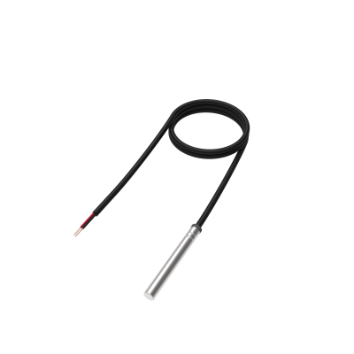
One of the implemented features for fleet management devices is a 1-Wire data protocol, which enables the connection of temperature sensors. It is a perfect accessory for temperature monitoring.
1-Wire temperature sensors is a great addition for your fleet management trackers in the following use cases:
- Thermostatic controls – maintain temperature near a desired set point.
- Thermally sensitive system – receive alerts when temperature enters or leaves pre-defined value.
- Consumer products – be assured that the goods which you are delivering will maintain high quality.

Product Specification
| NAME | DESCRIPTION |
|---|---|
| Interface | 1-Wire Interface |
| Wiring | Yellow wire – 1-wire data, Red wire - 1-wire Power, Black wire - ground. |
| Power Supply | 3V - 5,5V. Can be Powered from Data Line (parasitic connection) |
| Accuracy | ±0.5°C (-10°C to +85°C) |
| Temperature range | -55°C to 125°C (-67°F to +257°F) |
| Cable length | 8 meters |
| Tube | Stainless Steel, Waterproof |
| Serial Code | Unique 64-Bit |
| Other benefits | Stripped & Tinned Terminal, No External Components |
| Supported by |
FMB110, FMB120, FMB122, FMB125, FMU125, FMM125, FMC125, FMB130, FMU130, FMC130, FMM130, FMB140, FMB202, FMB204, FMB640, FMC640, FMM640, FMB150, FMB206, FMB225, FMB230, FMB240, FMB250, FMC13A, FMC150, FMC225, FMC230, FMC234, FMC250, FMC650, FMM13A, FMM150, FMM230, FMM250, FMM650 |
Installation
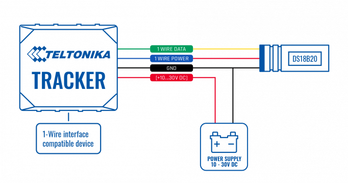
To connect the 1-wire temperature sensor you have to make sure to connect 3 PINs of the sensor to the PINs of your device correctly.
Up to 4 sensors can be connected to our devices simultaneously.
| PIN NUMBER | PIN NAME |
DESCRIPTION |
|---|---|---|
| 1 | 1-wire Data | Outputs temperature data via 1-Wire interface |
| 2 | 1-wire Power | Power supply for the sensor (can be left disconnected in parasitic connection. Works only with 1x Sensor). |
| 3 | GND (-) | Ground. |
Device configuration
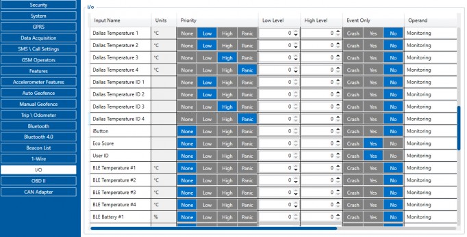
The device reads the sensor data automatically after the sensors are connected, however, the I/O elements are disabled by default to save data. To receive data to the server, make sure that the appropriate I/O elements(Dallas Temperature # / Dallas Temperature ID #) are enabled.
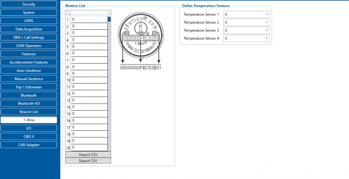
The first ID is the sensor that is connected first, which can be changed from the software side without disconnecting the sensors. It can be done by navigating to the 1-Wire section and assigning the IDs of the sensors in your desired order.


