TAT140 First Start: Difference between revisions
No edit summary |
|||
| (2 intermediate revisions by 2 users not shown) | |||
| Line 1: | Line 1: | ||
<b>{{{description|TAT140 is a device for asset tracking and additional protection against thefts of valuable goods, as well as it could be used in wide range of applications from tools tracking to container tracking.}}}</b>{{{pic|[[Image:TAT140-side- | <b>{{{description|TAT140 is a device for asset tracking and additional protection against thefts of valuable goods, as well as it could be used in wide range of applications from tools tracking to container tracking.}}}</b>{{{pic|[[Image:TAT140-side-2024-01-16.png|650px|right]]}}} | ||
| Line 58: | Line 58: | ||
<li>Windows 10</li> | <li>Windows 10</li> | ||
</ul> | </ul> | ||
| style="border: 1px solid #E8E8E8; border-bottom: 2px solid #E8E8E8; text-align: left; vertical-align: center; background: white;" | | | style="border: 1px solid #E8E8E8; border-bottom: 2px solid #E8E8E8; text-align: left; vertical-align: center; background: white;" |.NET Desktop Runtime 5.0.17 | ||
| style="border: 1px solid #E8E8E8; border-bottom: 2px solid #E8E8E8; text-align: left; vertical-align: center; background: white;" |32 and 64 bit | | style="border: 1px solid #E8E8E8; border-bottom: 2px solid #E8E8E8; text-align: left; vertical-align: center; background: white;" |32 and 64 bit | ||
| style="border: 1px solid #E8E8E8; border-bottom: 2px solid #E8E8E8; text-align: left; vertical-align: center; background: white;" |[https://dotnet.microsoft.com/en-us/download/dotnet- | | style="border: 1px solid #E8E8E8; border-bottom: 2px solid #E8E8E8; text-align: left; vertical-align: center; background: white;" |[https://dotnet.microsoft.com/en-us/download/dotnet/thank-you/runtime-desktop-5.0.17-windows-x64-installer www.microsoft.com] | ||
|} | |} | ||
| Line 159: | Line 159: | ||
===Mounting recommendations=== | ===Mounting recommendations=== | ||
* | The thoughtful placement of an asset tracker in a vehicle is key to ensuring seamless tracking and obtaining accurate location. We categorize the mounting places into three groups based on expected GNSS signal strength, helping you make informed decisions when choosing the asset tracker's location in the vehicle. | ||
<br> | |||
<br> | |||
<font color="#20c850"><b>High Signal Strength Locations:</b> </font> | |||
<br> | |||
* Front and rear bumper<br> | |||
* Glove box<br> | |||
* Behind the front or rear lights<br> | |||
<font color="#f5bf18"><b>Medium Signal Strength Locations:</b></font> | |||
<br> | |||
* Under the car <br> | |||
* Central console compartment<br> | |||
<font color="#f51818"><b>Low Signal Strength Locations:</b></font> | |||
<br> | |||
* Trunk <br> | |||
* Under the seat <br> | |||
* Door compartment<br> | |||
<br> | |||
[[File:Tat glovebox.jpg|alt=|left|thumb|546x546px|Glovebox]] | |||
[[File:Tat_lights.jpg|alt=|right|thumb|546x546px|Tail Lights]] | |||
[[File:Tat_center_console.jpg|alt=|left|thumb|546x546px|Central Console]] | |||
[[File:Tat_underneath1.jpg|alt=|thumb|546x546px|Underneath the car]] | |||
[[File:Tat_underneath2.jpg|alt=|center|thumb|890x890px|Underneath the car]] | |||
<br> | |||
Understanding these specific mounting places in each category will guide you in strategically placing GPS asset trackers, maximizing their battery life, and ensuring reliable periodic location monitoring.<br> | |||
It is always a good idea to position the antenna in such a way that there is as little metal and other obstructions in the way towards the outside of the vehicle. Similar to the example where device is placed behind the rear lights - <b>it is better if antenna is facing the plastic light fitting instead of facing upwards to the metal vehicle frame.</b><br> | |||
{| class="wikitable" style="border-style: solid; border-width: 0px" | |||
|+ | |||
|- | |||
| style="{{{TAT100_note|}}}text-align: left; background: #F6F6FB;" | [[Image:Bw_nb.png|50px]] | |||
| style="{{{TAT100_note|}}}text-align: left; background: #F6F6FB;" | While we have suggested categories and examples for optimal GPS tracker placement, it's essential to note that these are recommendations. <b>Every vehicle is unique, and factors like model, make, and construction materials can impact GPS signal reception differently.</b><br> | |||
Before installing a larger quantity of devices, <b>we strongly recommend conducting individual tests on your specific vehicles.</b> This will help identify the most suitable placement that aligns with your expectations and ensures optimal GPS signal strength.<br> | |||
|} | |||
[[File:TAT100_Antenna.png|border|class=tlt-border|500px]]<br> | [[File:TAT100_Antenna.png|border|class=tlt-border|500px]]<br> | ||
Latest revision as of 13:32, 7 May 2025
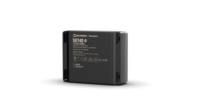
Main Page > Autonomous Trackers > TAT140 > TAT140 First StartTAT140 is a device for asset tracking and additional protection against thefts of valuable goods, as well as it could be used in wide range of applications from tools tracking to container tracking.
Know your device

Set up your device
How to insert Micro SIM card and start the device
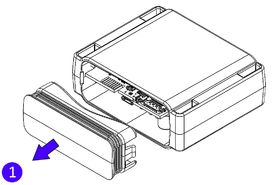
- Remove the cover.
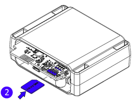
- Insert Micro-SIM card as shown with PIN request disabled or read Security info how to enter it later in Configurator. Make sure that Micro-SIM card cut-off corner is pointing forward to slot and chip is facing USB port.
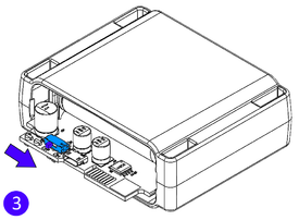
- Flip the switch to ON.
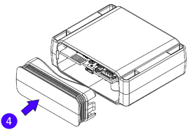
- Configure the device. When it is done, reattach the cover and push it in place.
| Micro-SIM card insertion/removal must be performed when device is turned off. Otherwise Micro-SIM card might be damaged or device will not detect it. |
PC Connection (Windows)
1. Remove the cover.
2. Turn on your device by flipping the switch to ON.
3. Connect device to computer using Micro-USB cable. You will need to install USB drivers, see “How to install USB drivers (Windows)” shown below.
4. You are now ready to use the device on your computer.
How to install USB drivers (Windows)
1. Please download COM port drivers from here.
2. Extract and run TeltonikaCOMDriver.exe.
3. Click Next in driver installation window.
4. In the following window click Install button. Setup will continue installing the driver and eventually the confirmation window will appear. Click Finish to complete the setup.
Configuration (Windows)
At first the device will have default factory settings unless you order pre-configured device. These settings should be changed according to the user's needs.
Main configuration can be performed via Teltonika Configurator software. Configurator operates on Microsoft Windows OS and uses prerequisite MS .NET Framework. Make sure you have the correct version installed.
| MS .NET requirements | |||
|---|---|---|---|
| Operating system | MS .NET Framework version | Version | Link |
|
.NET Desktop Runtime 5.0.17 | 32 and 64 bit | www.microsoft.com |
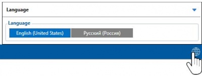
Downloaded Configurator will be in compressed archive. Extract it and launch Configurator.exe. After launch software language can be changed by clicking ![]() in the right bottom corner:
in the right bottom corner:
Configuration process begins by pressing on connected device:
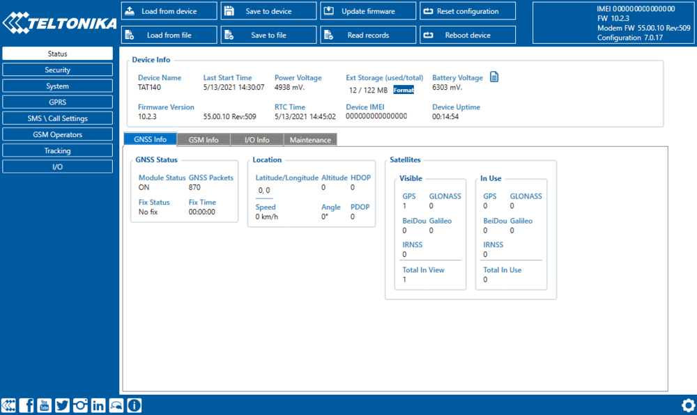
After connection to Configurator Status window will be displayed:
Various Status info tabs display information about GNSS, GSM, I/O, Maintenance and etc. TAT140 has one user editable profile, which can be loaded and saved to the device. After any modification of configuration the changes need to be saved to device using Save to device button. Main buttons offer following functionality:
 Load from device – loads configuration from device.
 Save to device – saves configuration to device.
 Load from file – loads configuration from file.
 Save to file – saves configuration to file.
 Update firmware – updates firmware on device.
 Read records – read records from device.
 Reboot device – restarts device.
 Reset configuration – sets device configuration to default.
Most important configurator sections are GPRS – where all your server and GPRS settings can be configured and Tracking – where data acquiring parameters can be configured. More details about TAT140 configuration using Configurator can be found here.
Important configuration notes
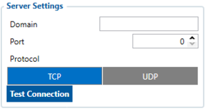
We strongly recommend testing the network connection from device to the server before adjusting TAT140 configuration to your needs.
Use the following steps to perform this test:
- Configure these parameters: APN, server Domain and server Port
- Save configuration to the device by clicking on a Save to device button;
- Initiate connection by pressing the Test Connection button
At this point, TAT140 device will create one high-priority record and initiates connection to the server immediately. If connection was not initiated, it can mean any of the following:
- Improperly inserted SIM Card
- Incorrect values are set to these fields: APN, Domain or Port
- GPRS functionality disabled by GSM provider
- No GSM coverage
- Server cannot be reached
Try solving this problem before proceeding with further device configuration.
Please note:
|
| CAUTION! Device usage with USB cable. In order to prevent device battery from running out of power, make sure USB cable is not connected, while testing the device. Continuous use of device, while connected to the USB cable will result in faster battery drain. |
Tracking scenarios
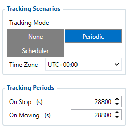
Periodic: This mode is used to get positioning data at fixed intervals. Configuration range is from 360 to 259200 (in seconds).
Please note:
|
Scheduler: This mode is used to get positioning data at fixed schedule. Device can send positioning data up to 6 times on set days.
Time Zone: Set tracking scenario time zone. Time zone can be set in range of -12h to +14h.
Main rules of Schedule setting:
- Intervals between time must be at least 6 minutes.
- Days of the week must be selected and highlighted for the device to send records according to set schedule.
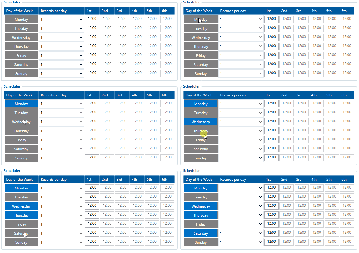
| Please note: Device has up to 3 min. hardcoded time to get fixed position while it's awake from a Sleep Mode. |
Mounting recommendations
The thoughtful placement of an asset tracker in a vehicle is key to ensuring seamless tracking and obtaining accurate location. We categorize the mounting places into three groups based on expected GNSS signal strength, helping you make informed decisions when choosing the asset tracker's location in the vehicle.
High Signal Strength Locations:
- Front and rear bumper
- Glove box
- Behind the front or rear lights
Medium Signal Strength Locations:
- Under the car
- Central console compartment
Low Signal Strength Locations:
- Trunk
- Under the seat
- Door compartment
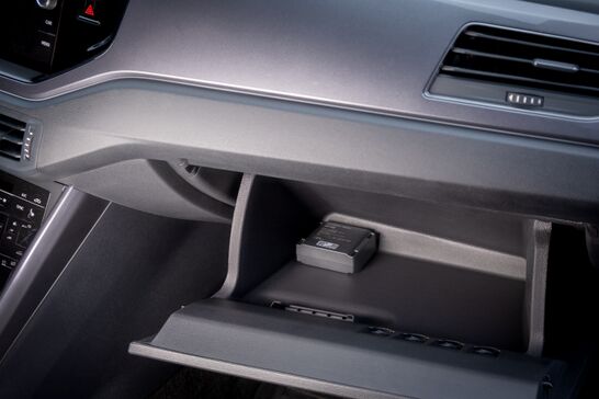
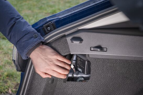
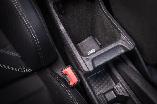
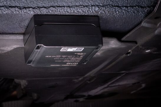
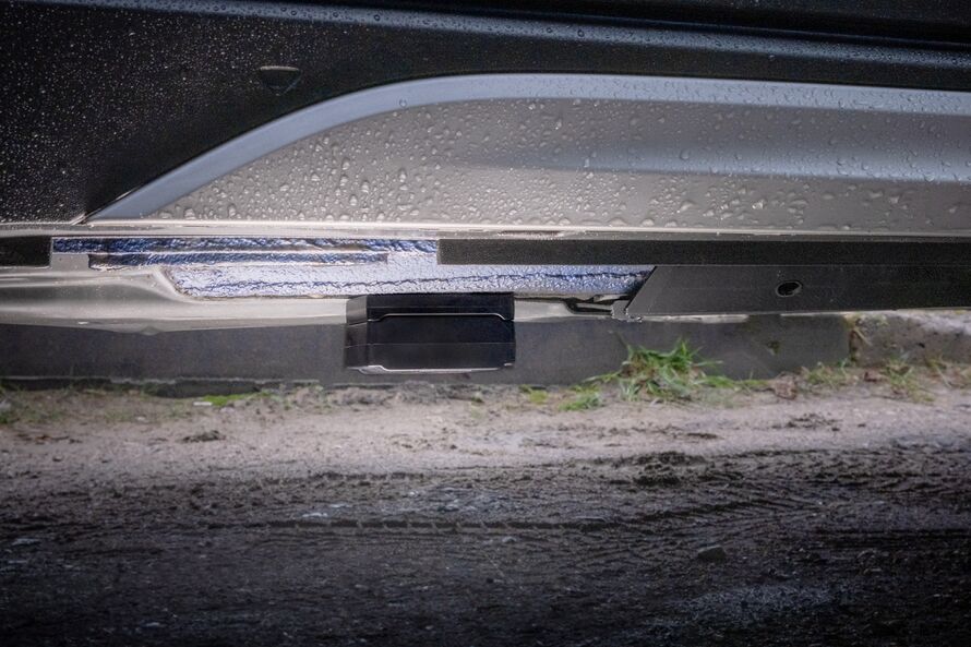
Understanding these specific mounting places in each category will guide you in strategically placing GPS asset trackers, maximizing their battery life, and ensuring reliable periodic location monitoring.
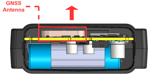
It is always a good idea to position the antenna in such a way that there is as little metal and other obstructions in the way towards the outside of the vehicle. Similar to the example where device is placed behind the rear lights - it is better if antenna is facing the plastic light fitting instead of facing upwards to the metal vehicle frame.
Quick SMS configuration
Please note:
|
Default configuration has optimal parameters present to ensure best performance of track quality and data usage.
Quickly set up your device by sending this SMS command to it:
" setparam 2001:APN;2002:APN_username;2003:APN_password;2004:Domain;2005:Port;2006:0"
GPRS settings:
- 2001 – APN
- 2002 – APN username (if there are no APN username, empty field should be left)
- 2003 – APN password (if there are no APN password, empty field should be left)
Server settings:
- 2004 – Domain
- 2005 – Port
- 2006 – Data sending protocol (0 – TCP, 1 – UDP)
Note: Before SMS command, two space symbols must be inserted.
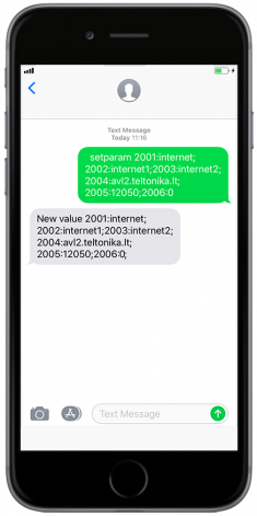
After successful SMS configuration, TAT140 device will synchronize time and update records to configured server.
Safety information
This message contains information on how to operate TAT140 safely. By following these requirements and recommendations, you will avoid dangerous situations. You must read these instructions carefully and follow them strictly before operating the device!

