ADAS First Start: Difference between revisions
No edit summary |
|||
| Line 104: | Line 104: | ||
[[File:ADAS_w_DOUT6.jpg]] | [[File:ADAS_w_DOUT6.jpg]] | ||
'''Two cameras FMC650 Installation with Relay''' | |||
. If you need to receive additional data from the Two cameras or one of them when the ignition is off, you can also connect the camera to a power source using the relay, to control the power supply by turning on/off the camera. To find information on how to configure DOUT, please visit [[FMB setdigout|FMB DOUT]]. | |||
. | |||
{| class="wikitable" | {| class="wikitable" | ||
Revision as of 07:45, 3 June 2024
Main Page > Video Solutions > Teltonika ADAS > ADAS First StartMain (front) camera unit preparation
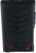
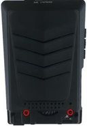
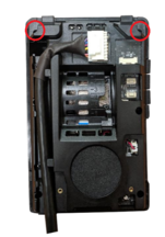
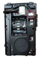
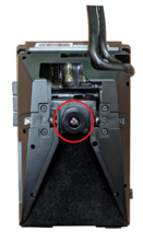
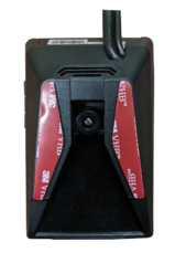
The main unit comes prepared for bus/large truck setup (cable routing) or vehicles with mostly vertical windshields. To set up the unit for an average truck or passenger vehicle, dismantle partially as shown below:
Vehicle installation
1. Clean the spots on the windshield with the alcohol wipe where you plan to mount the hardware. Remove the red 3M tape and mount the main unit underneath the rear-view mirror as centered (left/right) and straight as possible (if it must be off center by a few inches, that’s okay – measurements will be taken later). Be certain not to obstruct the drivers view.
2. Run the main-unit cable across the headliner and down to the driver side under-dash. This may require removing the A-pillar temporarily. Follow factory harnesses, always run behind any airbags.
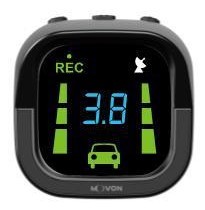
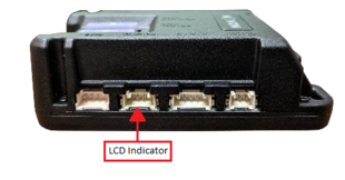
3. Attach the mount (from the plastic bag) and stick the LCD indicator on the windshield in the driver’s line-of-sight, usually close to the A-pillar so it can be easily seen and controlled if required. Run this cable down to the driver’s under-dash as well.
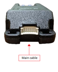
4. Once both cables are run to the under-dash, connect them to the provided PCI unit at the proper ports.
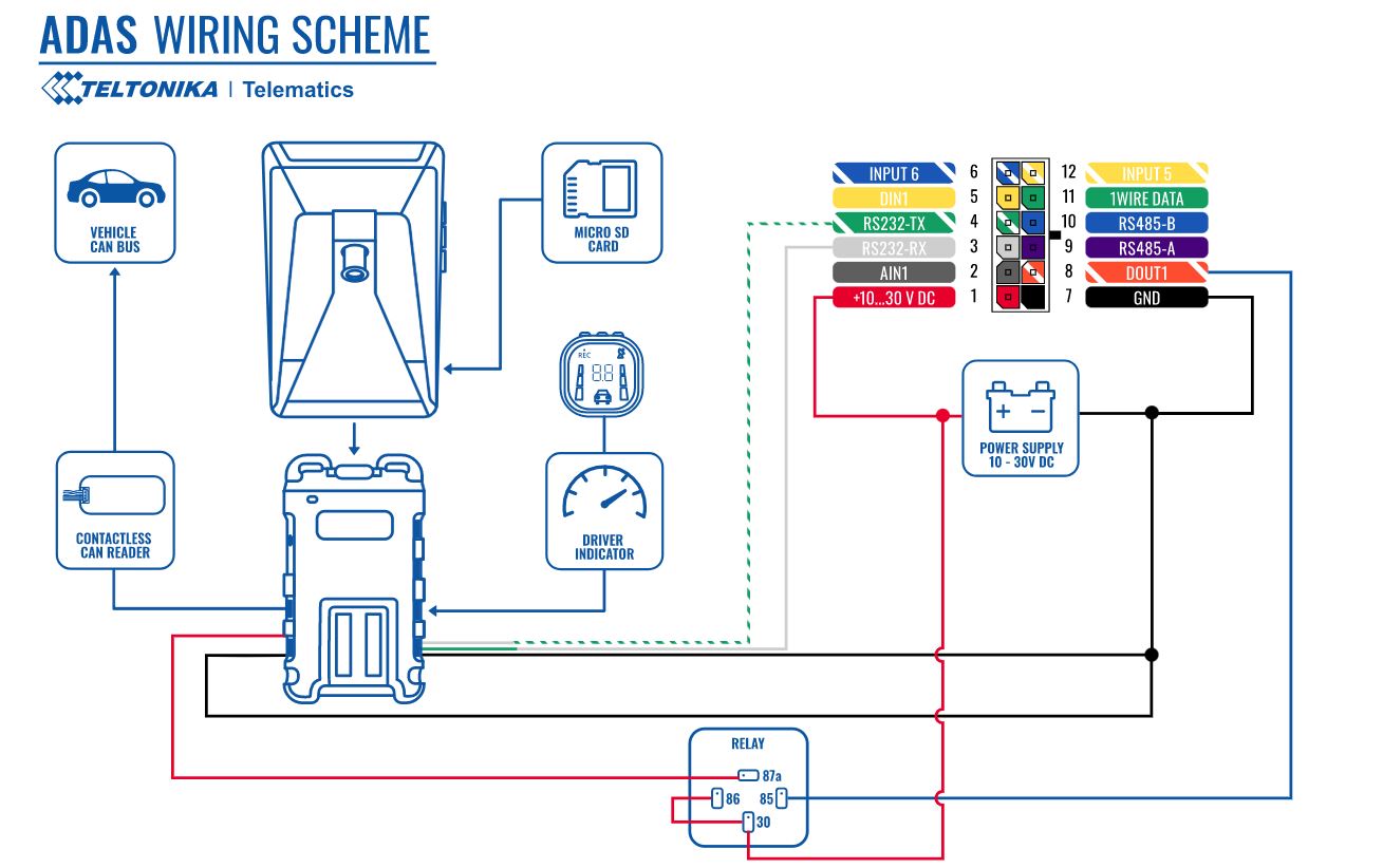
5. Connect the Teltonika FMx125,FMX225 tracker to the main unit using RS232 cable. Please refer connection scheme below.
Please note that camera must be connected to ignition source, in other way camera will drain battery
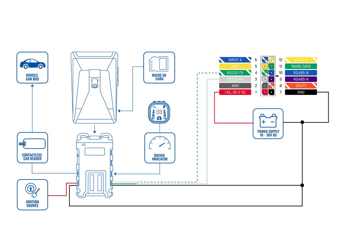
FMxy25 wiring with DOUT Please note, that alternative wiring with DOUT is possible, in order to receive additional data from ADAS while the ignition is off, but the key is turned to the ACC position. That way it would be possible to control the power supply by turning on/off the camera. To find information on how to configure DOUT, please visit FMB DOUT.
| PIN NUMBER | PIN NAME | DESCRIPTION |
|---|---|---|
| 4 | RS232-Tx | ADAS output for data transmission through RS232 |
| 3 | RS232-Rx | ADAS input for data reception through RS232 |
| 1 | VCC (9-36V) (+) | Power supply for the ADAS |
| 7 | GND (-) | Ground |
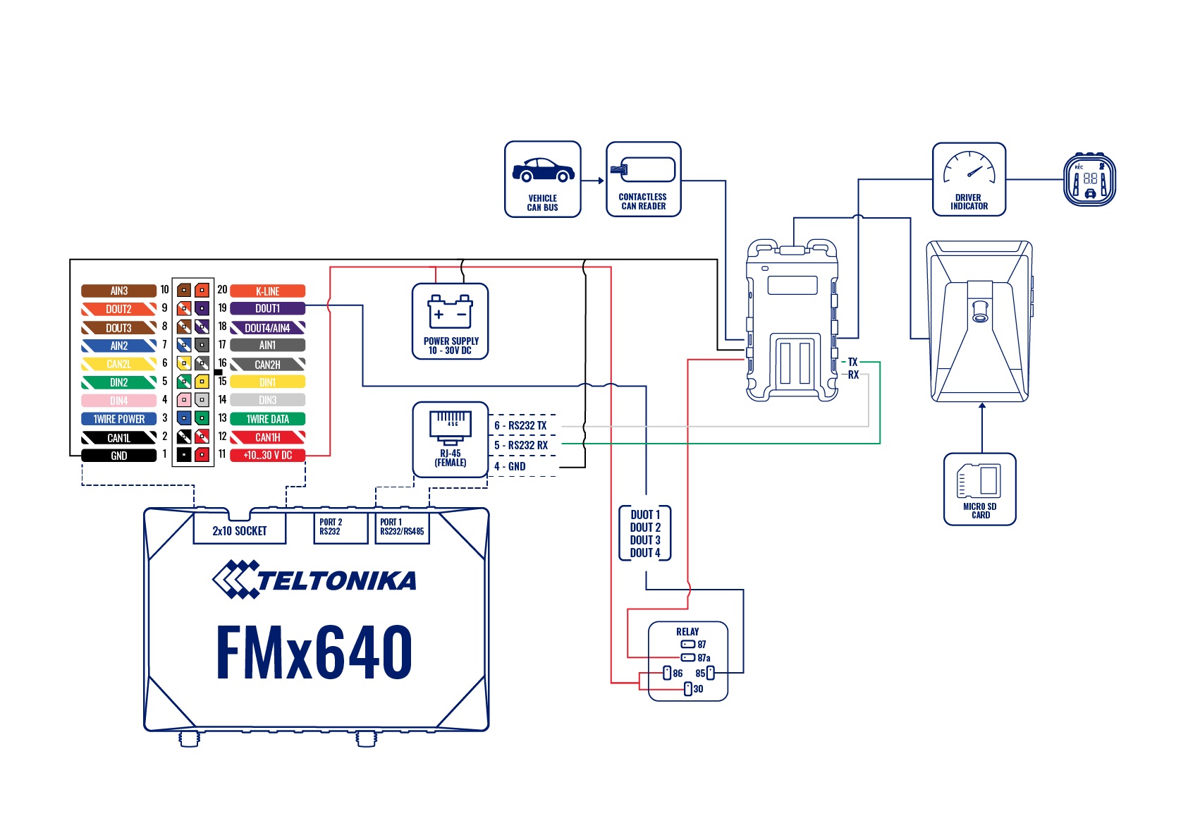
For FMX640 + ADAS connection
Please note that camera must be connected to an ignition source, in other way the camera will drain battery
Also, some RJ45 cables have two modifications, some have RS232 output on 3/4 pins some on 5/6 pins
For FMX640 devices, RJ45 cable is required with one end cut and loose. Connect the RJ45 cable to the FMX640 device's port 1 or port 2, both slots have RS232 support. Once connected, the other end of the cable should have pin 5-Rx, and 6-Tx shaved and connected to ADAS camera Rx and Tx cable. For the rest of the connection please refer to the picture below.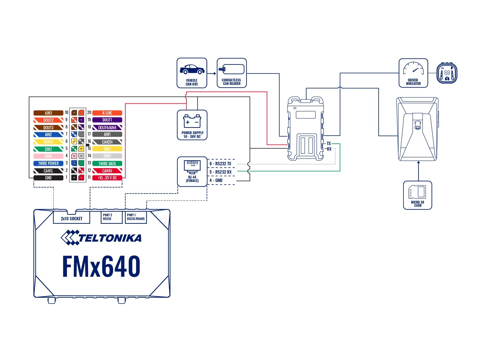
ADAS connection with relay If it is necessary to receive additional data from the ADAS when the ignition is off but the key is inserted and turned to the ACC position, you can do it by connecting the camera to a power source using a relay in order to control the power supply by turning on/off the camera. To find information on how to configure DOUT, please visit FMB DOUT.
Two cameras FMC650 Installation with Relay . If you need to receive additional data from the Two cameras or one of them when the ignition is off, you can also connect the camera to a power source using the relay, to control the power supply by turning on/off the camera. To find information on how to configure DOUT, please visit FMB DOUT. .
| PIN NUMBER | PIN NAME | DESCRIPTION |
|---|---|---|
| 6 | RS232-Tx | ADAS output for data transmission through RS232 |
| 5 | RS232-Rx | ADAS input for data reception through RS232 |
6. Connect the provided Power/Ground harness connection to a chassis ground (black wire) and Ignition source (red wire). The circuit must provide ~3 Amp @12v. Connect the plug to the PCI unit at the ‘Power’ port.
Installation: for CAN-equipped vehicles
Many vehicles are available in the database for using the CAN bus for vehicle signals (turn signals, brake and speed sense). This makes for a much faster installation. See below for checking the availability of a downloadable CAN file for your vehicle. NOTE: not all vehicles are available on the database currently, even if the vehicle has CAN. The list is constantly updated, so if the vehicle isn’t there now, it may be later. The installation may still be completed using analogue connections instead of CAN – see next section.
Check to see if there is a CAN file available by opening a Chrome browser and going to http://info.mdas.co.kr/customer/login
USER: [email protected]
PASS: mDaSdataBase
1. Choose the vehicle make and model into the selector at the left.
2. Click the page icon (at right) and the database information will show CAN wire location information (if available) and download the ‘CAN File Download’ file at the bottom. NOTE: this filename will always be ‘mdasinfo.dat’ and cannot be renamed – so if you’re installing another ADAS and using this computer to set up, make a separate file folder (every time) with the vehicle year and model, and put this file inside of it.

3. If there is a CAN file available, connect the provided CAN harness (contactless reader) to the (transmission) CAN bus wires – either where stated or at the OBD2 port, typically pins 14 & 6, if the vehicle is available on the database only.

NOTE: this connection uses inductance. There is no need to strip the CAN wires – just open the black box, lay the CAN High and Low in the channels, then close the box.
4. Connect the 4-pin plug from the CAN harness to the ‘CAN’ port on the PCI unit.
If the vehicle is not listed in the database, you must use the provided Analog harness, see next section. NOTE: vehicles that are 1 year (or so) off, may still work for CAN access!
Installation: For Analog signals (no CAN)
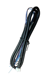
If the vehicle has no CAN bus or there is no CAN file available, you must tap the turn signal (left and right), brake and speed signal manually (various locations).
1. With a digital multimeter or test light, locate the brake signal wire that activates when the brake is pressed (the vehicle may need to be ON). Connect and insulate the black/white wire to this vehicle’s wire. This may be a (+) or (-) signal.
2. With a digital multimeter or test light, locate the left turn signal wire that activates with the left turn signal. Connect and insulate the blue/white wire to this vehicle’s wire. This may be a (+) or (-) signal.
3. With a digital multimeter or test light, locate the right turn signal wire that activates with the right turn signal. Connect and insulate the blue wire to this vehicle’s wire. This may be a (+) or (-) signal.
4. Locate the VSS wire. Connect and insulate the brown/white wire to this vehicle’s wire.
NO other wires are required for typical installation – ground the remaining wires.
ADAS Calibration
ADAS Calibration requires:
- a laptop with an internet connection and a browser
- micro-USB cable
- tape measure
- parking the car with a clear, open stretch of about a 45 meters unobstructed view (try to park close to your facility to keep the internet connection accessible – at least during the calibration driver installation)
- a partner to drive the vehicle while speed correction is performed
Before beginning, insert the provided micro-SD card into the main unit in the location shown below until it clicks and turn the Ignition ON. Wait for the prompt, then press and release the center button one time. After the successful prompt and the unit reboots, continue to step 1.
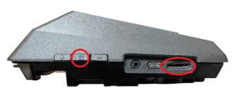
1. Park the vehicle in a spot with a clear stretch of unobstructed line-of-sight (about 45 meters). Leave the vehicle running
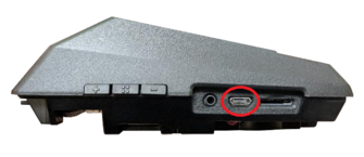
2. Connect the USB cable to the Mirco-USB port on the side of the main unit (windshield) and the other end to the laptop. If on a windows 10 machine, it should automatically install the required driver. If not or on an older machine, go to movon.co.kr, go to the ‘ADAS’ tab at the top then to ‘Downloads’ under Support. Download the appropriate zip file (contains driver) and extract it fully for your version of Windows OS (if using the 7/8 driver, install the .exe file). If WIN10, once downloaded, disconnect/reconnect the USB and it should automatically install, or find the unit in Device Manager and right-click, Update Driver and browse for driver locally.
3. Open Chrome browser again and type in ’10.0.0.1’ into the URL bar. If the driver was installed properly, the calibration screen will appear. Input credentials and press LOGIN USER: admin PASS: 1234
4. Select Vehicle Signal Type: there are several wiring options for installation: CAN-BUS / Analog (GPIO) / GPS (Speed). Select the proper calibration option based off which was installed: CAN (if CAN file is available), Analog (if analogue signals were tapped)
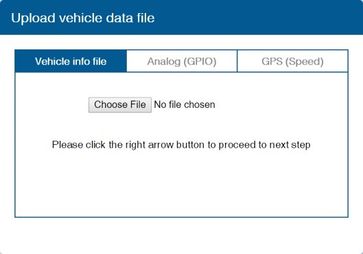
Vehicle Data File (CAN-BUS)For CAN-BUS connection, choose the ‘Vehicle info file’ tab and select ‘Choose File’ to upload the previously downloaded ‘mdasinfo.dat’ file (see ‘CAN-Equipped vehicles’ section).
Camera location and Vehicle Measurement
Camera location and vehicle measurement can affect ADAS performance. It`s very important put accurate data for the best performance.
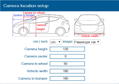
| Camera Option | Description |
|---|---|
| Camera Height | Distance from ground to the center of camera lens. |
| Camera Center | Distance from the center of windshield to camera lens
“-“: Left Side / “+”:Right Side (If ADAS is attached 5cm to the right from the center, input 5. If ADAS is attached 5cm to the left from the center, input -5.) |
| Camera to Wheel | Distance from the camera to the center of the wheel.
For trucks or buses, some vehicles’ wheels are located behind. In this case, please input 20cm. |
| Vehicle Width | Distance between the wheels.
Measure the distance from the left outside border to the right outside border of the wheels. |
| Camera to bumper | Distance from the camera lens to the end of the bumper.
For trucks or buses, it is recommended to input 300 if a sensitive FCW warning is needed. |
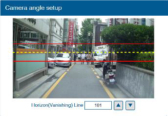
Camera angle – adjust the camera angle to locate the horizontal between the red guidelines.
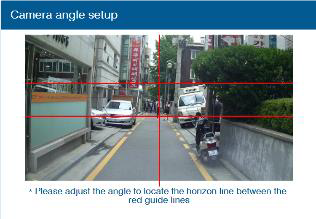
In case of indoor installation or somewhere you cannot see the horizon properly, use the same data to "Camera Height”. Mark the same height on the wall apart about 3 ~ 5 meters from the vehicle.
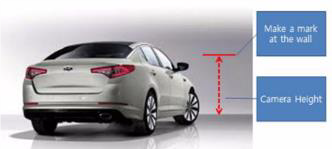
Fine Camera Angle - For better accuracy of ADAS, locate the yellow dotted line in the horizon as close as possible.
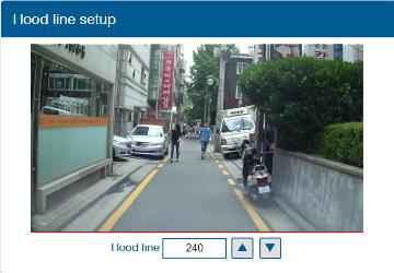
Hood Line - Locate the red line at the end of the vehicle’s hood line to remove the useless area.
Please follow the link for video instructions: https://www.youtube.com/watch?v=93wrc6j9aqA

