Universal Device Test Guide
Introduction
This Universal Device Test Guide helps new users to get acquainted with Teltonika Telematics Fleet Management devices and to test basic functions in 5 easy steps.
The guide also provides information about specific use cases, advanced features, and software solutions.
Use the Teltonika WIKI, Teltonika Telematics Community page and our Official Youtube Channel to get more in-depth information and answers to any other questions. Our highly professional support engineers are always willing to help - they can be reached via HelpDesk.
Basic Testing
Here, we will go through five easy testing steps which will introduce you to Teltonika Telematics devices.
We will cover everything you need to start using the device - from inserting a SIM card and powering the device, to receiving GPS track information from your vehicle to the server.
Equipment and software required to follow this guide:
- Teltonika Telematics device with the included accessories
- Pry tool to open the device enclosure (if needed)
- Working, registered SIM card (type depends on device)
- Power supply unit capable of supplying 10-30 VDC.
- Personal computer with Windows OS, internet connection and:
- One of the following:
Below is the General Quick Start Guide video. It shows steps that can be applied to most Teltonika Telematics devices.
Note: The video shows a configuration procedure with a Truphone SIM and APN. If you use other service providers, please contact them for exact APN details.
STEP 1: Prepare the Device
Result: The SIM card is inserted into the device and the internal battery is connected.
Requirements for this step:
- Teltonika Telematics device with the included accessories
- Pry tool to open the device enclosure (if needed)
- Working, registered SIM card (type depends on device)
 |
Attention! Power off the device before inserting/removing the SIM card. Disconnect all power sources - internal battery and external voltage. Otherwise, the SIM card may be damaged or the device may not detect it. |
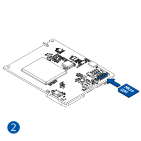
All Teltonika Telematics devices use SIM cards to enable telecommunication. It is impossible to get any data from the device to a server without a SIM card. Different devices may use different SIM card types: mini-SIM, micro-SIM, nano-SIM, eSIM (soldered during manufacturing).
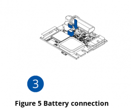
Some devices have an internal battery. It provides power to the device when no other power sources are available. The battery may not be connected when you receive your device (check your order details). The internal battery must be connected before first use.
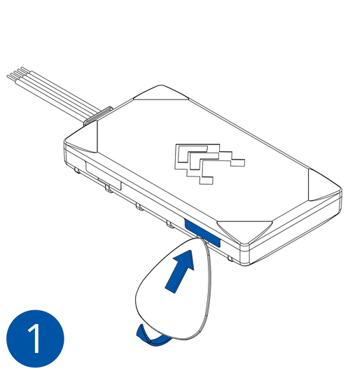
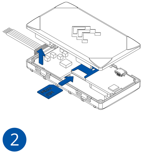
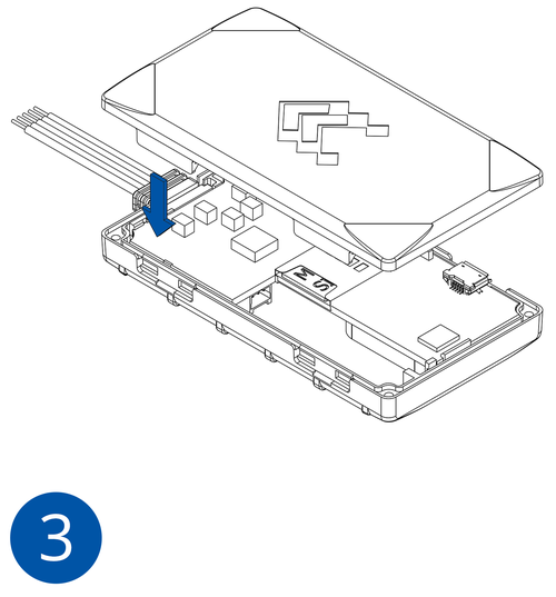
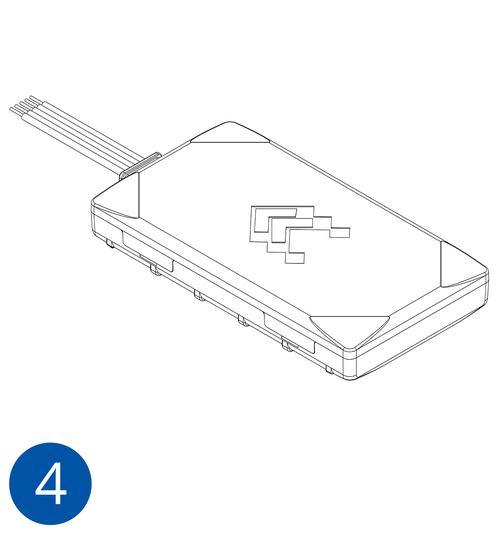
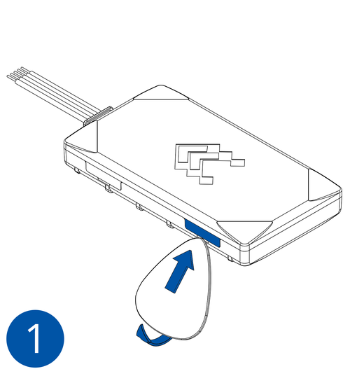
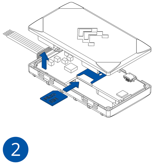
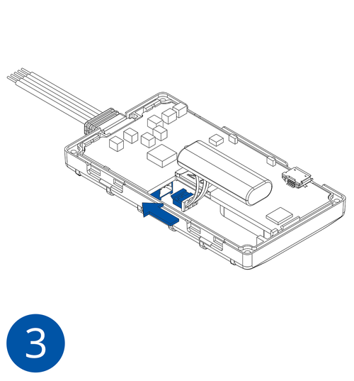
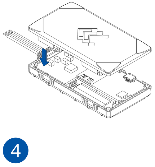
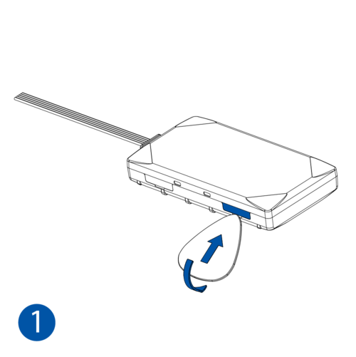
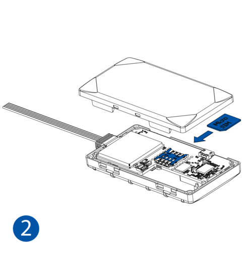
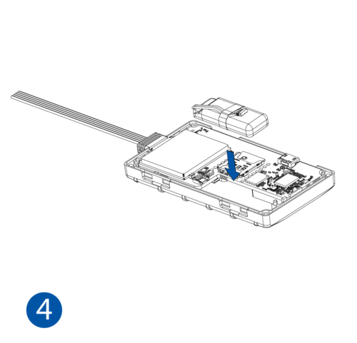
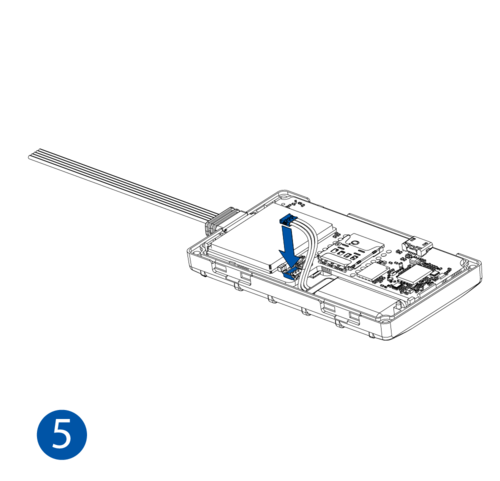
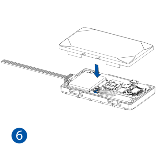
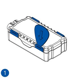
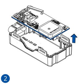
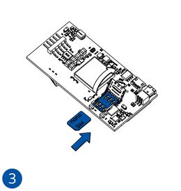
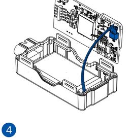
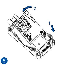
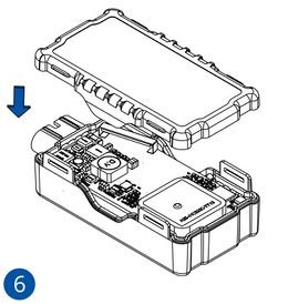
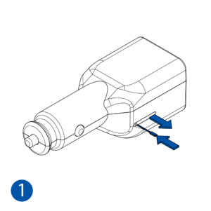
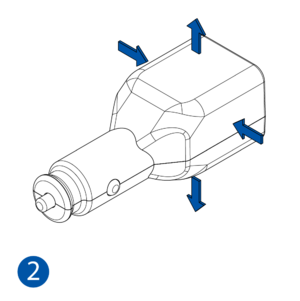
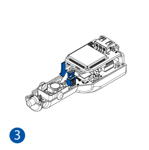
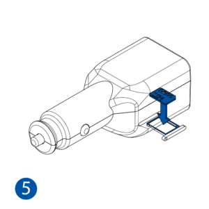
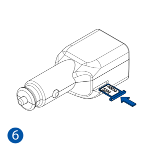
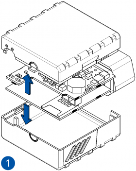
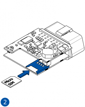
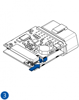
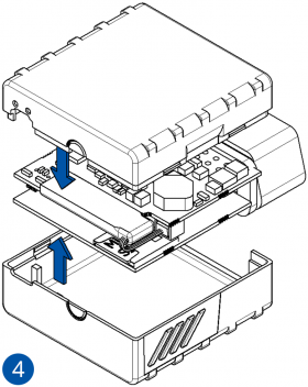
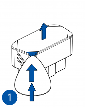
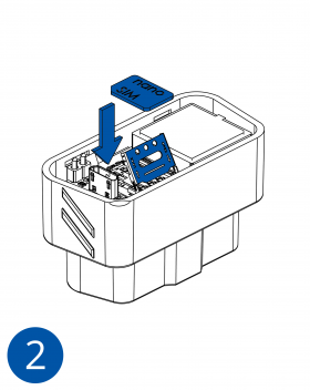
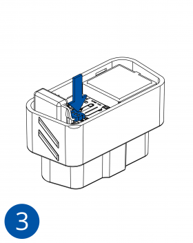
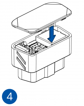
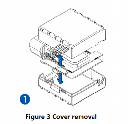
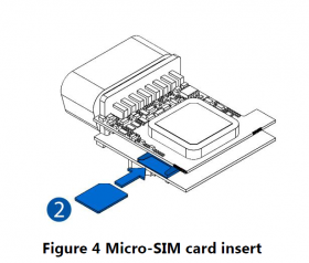
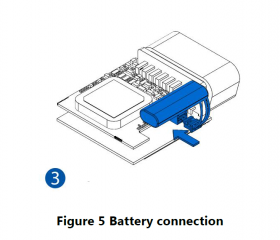
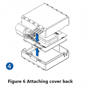
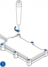
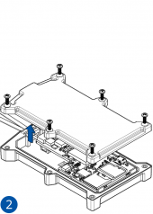
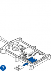
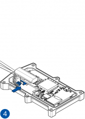
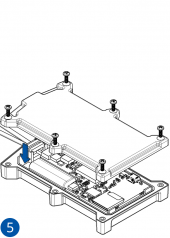
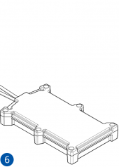
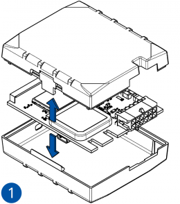
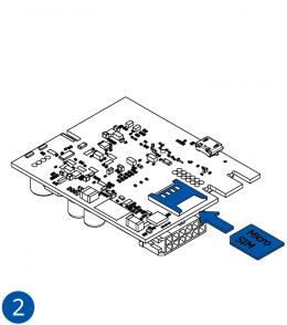
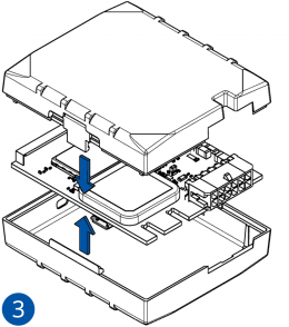
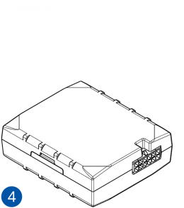
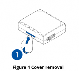
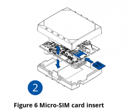
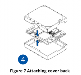
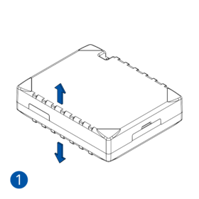
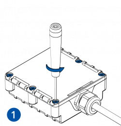
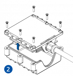
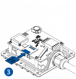
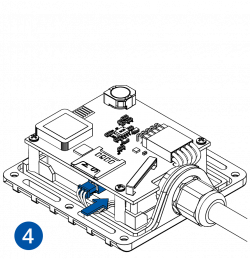
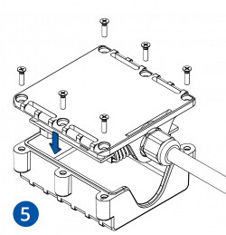
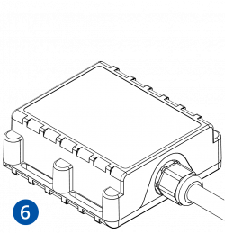
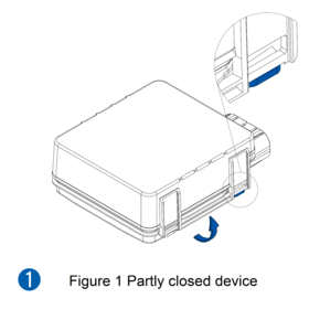
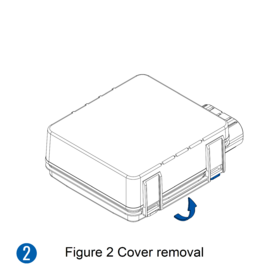
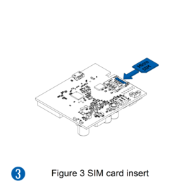
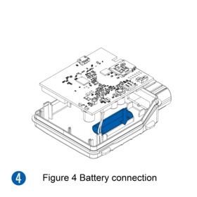
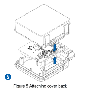
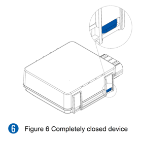
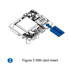
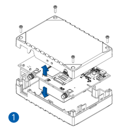
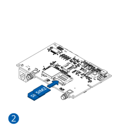
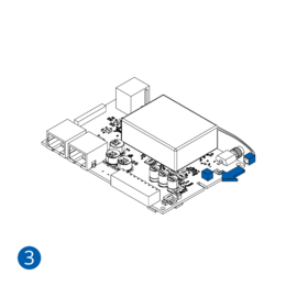
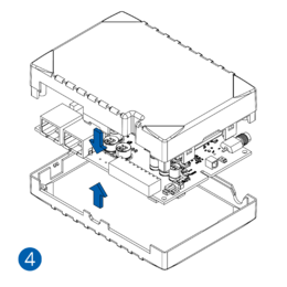
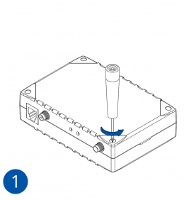
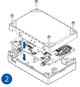
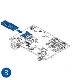
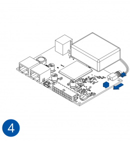
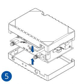
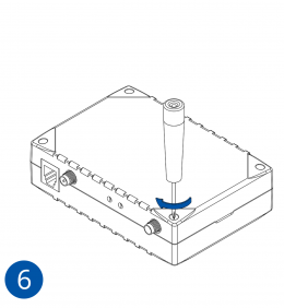
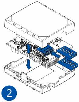
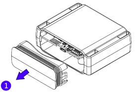
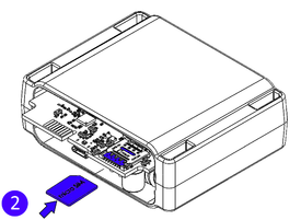
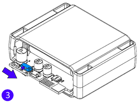
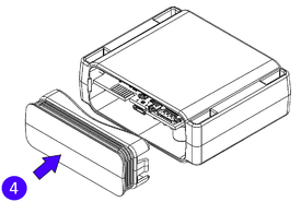
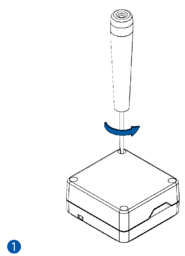
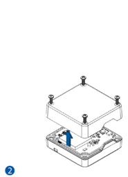
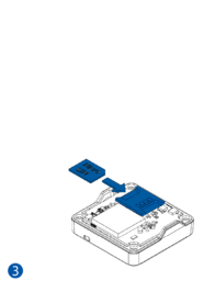
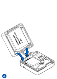
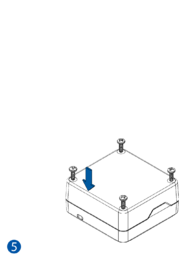
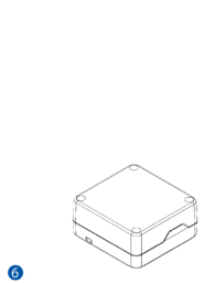
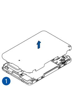
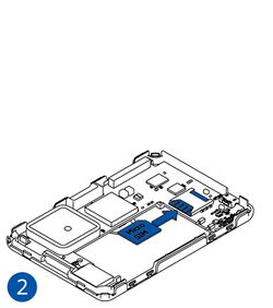
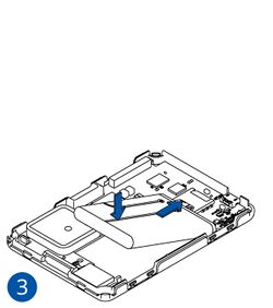
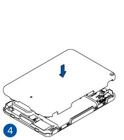
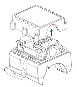
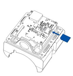
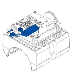
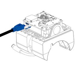
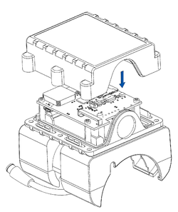
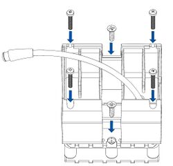
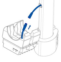
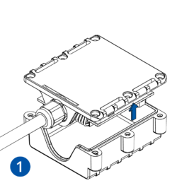
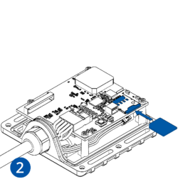
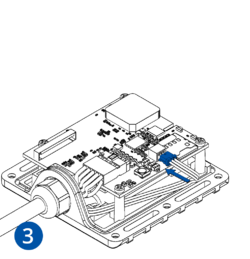
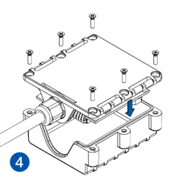
Pictures in the table below show how to prepare different devices.
To insert the SIM card and connect the battery:
- Carefully remove the device cover - use a pry tool if needed.
- Some devices have an external SIM card slot. In these cases, first open the slot.
- Insert the SIM card into the SIM card slot. Orient the SIM card correctly - align the cut-off corner.
- Connect the battery. Position the battery so that it does not mechanically interfere with other internal components when the cover is closed.
- Some devices require battery cable management and precise steps to insert the internal components back into the enclosure.
- Re-install the device cover.
The device is now ready to be connected to the PC.
Advanced trackers
STEP 2: Connect the Device to PC
Result: The device is powered with a power supply and connected to the PC.
Requirements for this step:
- Prepared Teltonika Telematics device
- Personal computer with Windows OS, internet connection and:
- COM port drivers (download .zip file here)
- A power supply unit capable of supplying 10-30 VDC.
One of the ways to control your device is by connecting it to a PC via USB or Bluetooth®. Before connecting, power must be provided to the device by a power supply.
For device-specific information about connecting to PC, see Wiki Knowledge Base → Your device model → First Start → PC Connection (Windows).
To connect the device to the PC:
- Install COM port drivers.
- Before connecting the device to the power supply and turning the power supply on, make sure that the power supply will provide voltage in the range of 10-30 VDC, e.g. 12 VDC.
- Do not turn on the power supply. Connect the device to the power supply using the provided power cable.
- Some devices can be powered and configured using only a USB cable, without the need for a separate power supply (in this case, skip to the last step).
- Now, turn on the power supply – device LEDs should start blinking (see LED Status).
- Connect the device to the PC via the provided USB cable or Bluetooth®.
The device is now powered and connected to the PC.
STEP 3: Configure the Device
Result: Device is configured to generate and send records to the specified server.
After powering up your device, it should be configured to meet your needs. Here you will find steps on how to prepare your device for a first start.
Configuration
At first, the device will have default factory settings set. These settings should be changed according to the user's needs.
Main configuration can be performed via Teltonika Configurator software. Get the latest Configurator version from here. Configurator operates on Microsoft Windows OS and uses prerequisite latest MS .NET Framework.
The configuration process begins by pressing on the connected device:
After connection to Configurator Status window will be displayed.
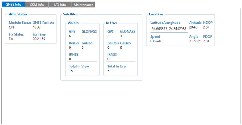
In the status window, you will be able to see crucial information that influences device operation such as GNSS and GSM statuses.
GNSS Info tab contains GNSS Status, Satellites, and Location information.
- GNSS Status describes whether the module is ON, received/sent GNSS packets count, FIX status and FIX time
- Satellites provide you information about visible and currently in-use satellites
- Location provides you the coordinates, speed, altitude, and angle of your current location.
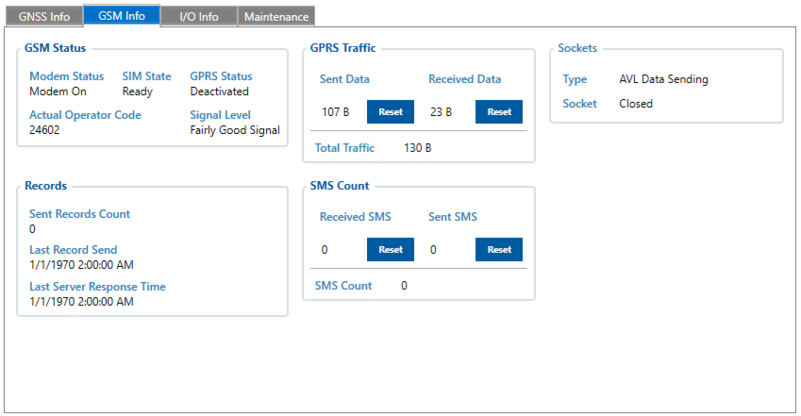
GSM Info tab contains GSM Status, Records, GPRS Traffic, SMS Count, and Sockets information
- GSM Status describes modem status, SIM state, GPRS status, signal level, and operator code
- Records provide you information about sent records count and the date of the last record sent/server response
- GPRS Traffic contains information about data usage
- SMS Count shows you sent/received SMS count
- Sockets provide status about AVL Data server communication
Various Status window tabs display information about GNSS, GSM, I/O, Maintenance and etc. configuration can be loaded and saved to the device. After changing the configuration, make sure that modifications are saved by clicking "Save to device" button. To restore default configuration, click "Reset configuration" button.
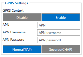
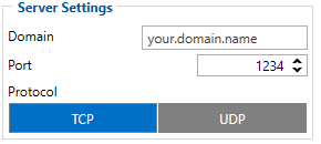
The most important configurator section is GPRS – where all your server and GPRS settings can be configured and Data Acquisition – where data acquiring parameters can be configured.
| Illustration | Parameter ID | Description |
|---|---|---|
|
2001 | Access Point Name is a gateway between mobile operator and public internet.
It can be obtained from your SIM card provider. When correct APN settings will be entered device will connect to the internet. Note: we do have an auto APN functionality, which is described here |
| 2003 | APN password (if there are no APN password, empty field should be left) | |
| 2002 | APN username (if there are no APN username, empty field should be left) | |
|
2004 | Domain/IP of destination server |
| 2005 | Port of destination server | |
| 2006 | Data sending to destination server protocol (0 – TCP, 1 – UDP) |
Note: If you do not have GPS tracking service yet, you can use Teltonika TCP/UDP listener to receive data from the device and Teltonika parser to parse received information. Software can be downloaded from here. Archive password: 1234
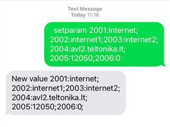
If you do not want to configure your device via configurator, you can quickly set up your device GPRS settings by sending this SMS command to it:
" setparam 2001:APN;2002:APN_username;2003:APN_password;2004:Domain;2005:Port;2006:0"
Note: Before SMS text, two space symbols should be inserted.
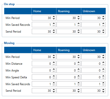
After successful GPRS/SERVER settings configuration, device will synchronize time and update records to the configured server according to the Data Acquisition time intervals. The default configuration has optimal parameters present to ensure the best performance of track quality and data usage. However, for testing, we do recommend these Data Acquisition settings:
The device will generate periodic records and send them to the server based on Data Acquisition settings.
Using these settings, the device will make a periodic record every 30 seconds and will send it every 30 seconds
After testing, Data Acquisition settings should be configured according to your needs.
The device will switch operating mode between On Stop and Moving based on configured corresponding movement source status.
More details about devices configuration using Configurator and more information about your particular device can be found Teltonika WIKI documentation. Click on your device -> Configuration.
STEP 4: Mount the Device
Result: Device is mounted in an optimal location, allowing it to have good GNSS and GSM connectivity.
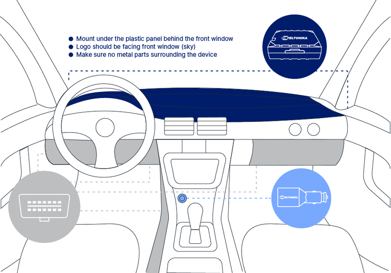
Different types of devices have specific mounting instructions: some of them are simple plug-and-play, while other hard-wired devices require professional installation. Please find your specific device mounting instructions Teltonika WIKI documentation. Click on your device -> First Start -> Mounting recommendations and precautions.
Installation instructions
STEP 5: Track the Device
Result: User is able to track his device on the tracking platform.
Last but not least step for Basic Testing would be to get data/track from your device.
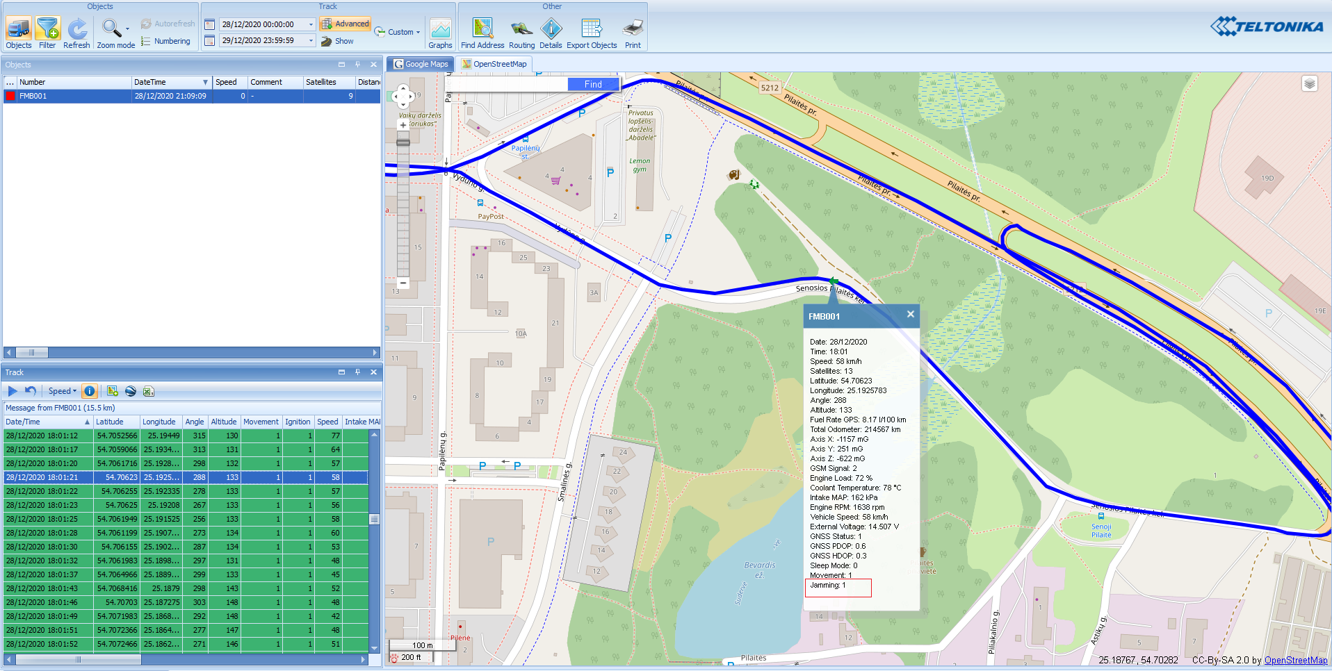
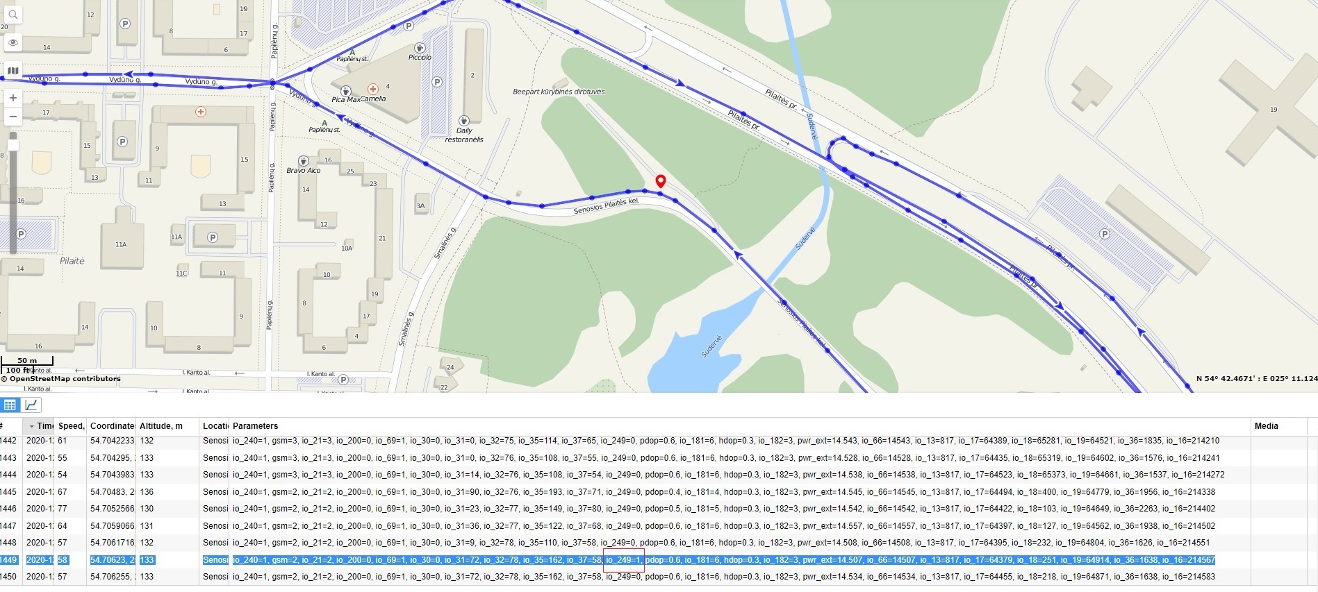
This can be done by using either simple TCP/UDP listeners or pre-made tracking platform like listed here.
Below you can find steps on how to set up a simple TCP/UDP listener on your personal computer.
- Open TCP/UDP port
- Go to Java Parser First Start Guide
Below you can find pictures of how the track looks on different pre-made tracking platforms:
Advanced Testing
In this chapter, we will review advanced device functionalities to get the most out of your Teltonika Telematics device. We will go through some of the specific, widespread use cases, however, keep in mind that device scenarios are not limited to just that. Available device functions can accomplish a much wider range of application scenarios, which will be limited only by your imagination!
Advanced SMS capabilities
Teltonika devices have a broad SMS usage spectrum including advanced device configuration and debugging. A full list of SMS commands can be found here.
For example, one of the most widely used SMS command for configuring the device is "setparam". Below you can see a description of this command:
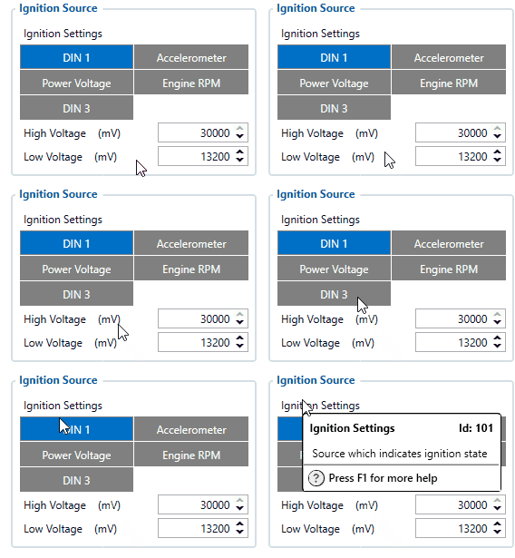
Setparam changes parameter value. Command structure is: "<SMS_Login><Space><SMS_Password><Space>setparam<Space>[Parameter ID] : [New Parameter Value] ; [Parameter ID] : [New Parameter Value]..." Parameter ID consists of 3 or 5 digits. A detailed list of parameters and identifiers can be found here.
|
You can also find parameter ID by hovering the mouse pointer over specific parameter in the configurator. |
SMS command is limited to 160 characters.
Example:
"setparam 101:1" will change ignition setting to "DIN1".
Answer:
"Param ID:101 Value:1"
Example:
"setparam 101:2;138:1" will change ignition setting to "Accelerometer" and movement source to "Ignition"
Advanced Use Case configuration
Our devices can be as simple or as complicated as you want them to be. Having one firmware and one configurator for all the devices allows different devices to be used in a broad spectrum of use cases. Other use cases have specific devices assigned.
To show how easy it is to use our devices in different use cases we prepared a technical description of what steps are needed to integrate our device into your use case.
Each category explains what parameters have to be configured and why as well as showing examples of what information you should expect on your server and how to read it.
General use case descriptions, an overview of the most commonly used solutions, their topologies, and possibilities, provided on the Teltonika website USE CASES.
Specific technical use case instructions can be found here.
Solutions
In this section, we will get acquainted with our most useful and simple to utilize solutions which will provide remote access, management, and control of your device as well as external devices like tachograph.
FOTA WEB
FOTA WEB – a brand new and exciting solution for remote access to your Teltonika Fleet management devices! FOTA WEB enables firmware upgrades, configuration changes, remote device debugging of FMx devices, as well as CAN adapter updates without a need of a dedicated application – everything is achieved through your regular Web browser, from any device. By default, the device connects to FOTA WEB every 720 minutes (parameter is configurable). For more information click here. If you would like to have your own FOTA WEB account, please contact your Sales Manager. Short video about FOTA WEB.
Moreover, we also have a desktop FOTA solution: desktop FOTA is the predecessor of FOTA WEB, which is mainly used for updating EOL (End-Of-Life, - FM5300, FMA120, etc.) devices. We strongly advise to use our newest FOTA WEB platform for OTA changes.
Note: FOTA WEB meets all GDPR requirements thus we do not store, track or analyze your personal data.
WEB Tacho
Teltonika WEB Tacho is an online service that allows to remotely download Tachograph files from supported tachographs, using Teltonika professional trackers. Files are stored on server, in defined format (.DDD, .V1B, .C1B, .TGD). Files can be downloaded – directly from the website, receive in Email, receive to a defined FTP server. For more information click here. If you would like to have your own WEB Tacho account, please contact your Sales Manager.
Protocols
Our devices communicate using unique Teltonika's protocols. Protocols are applied for different usage scenarios using Codecs. Each Codec has its own structure and application scenario. A codec is a device or computer program for encoding or decoding a digital data stream or signal.
Data sending protocols
Each Codec used by Teltonika devices has a different purpose. For example, Codec 8 Extended is main FM device protocol used to send data to server, while Codec 12 is used for device-server communication using GPRS messages. All information about Teltonika's communication protocols used by FM devices can be found here.
Protocols implementation
TCP/UDP listener and AVL Records parser, which source code could be used as a template for developing your own server, can be helpful for implementing protocols. A full software pack can be downloaded from here. Archive password: 1234.
Each device I/O parameter has its own unique ID, which is called AVL ID. Once the TCP/UDP listener and AVL Records parser are implemented, received AVL IDs descriptions can be checked in the AVL ID list page for your specific device (for example: FMB120 ).


