FLEET MAINTENANCE SCHEDULES (DELIVERY)
Project description
Delivery service is a business where efficiency is everything. Customers expect their goods to be delivered in time and meeting these expectations is a must if the company wants to make a solid profit. Anything what causes delays should be minimized or eliminated. Facilitated by GPS devices, timely vehicle maintenance can greatly reduce the number of irregularities and, thus, help the business grow.
We glad that you decide to test our “Fleet Maintenance Schedules (Delivery)” solution.
Here you will find how to prepare and to test this solution.
What you need for a solution?
- Teltonika FM device which is compatible with this use case and have OBD connection and can read OBDII data. Recommended devices: FMB001, FMC001, FMM001, FMB003, FMB002. Also, it is possible to use FMP100 via Bluetooth function but it requires Bluetooth OBDII dongle.
- The SIM card in order to get data to your server.
- FOTA to remotely send the configuration to the device.
- Teltonika Configurator to set up FM device correctly for the solution.
Installation
Connecting the device to the vehicle:
- Before connecting the device to the OBDII socket, make sure that ≥3A fuse is present on OBD connector power supply.
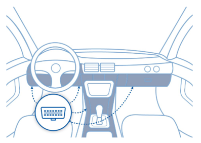
- Find OBDII connector in your vehicle ( Figure 1.) if you need more accurate location please visit Location of OBD plug.
Configuration
1. Prerequisites:
1.1. Read through First start guide
1.2. Understanding of possible Sleep modes.
2. Configuring Fleet Maintenance Schedules:
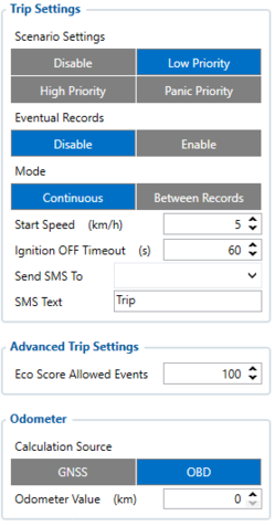
Parameter ID - Parameter name
Trip settings:
- 11800 - Scenario priority (0 - Disable, 1 - Low, 2 - High, 3 - Panic).
- 11801 - Eventual settings (0 - Disable, 1 - Enable), if disabled - trip settings will come with periodical data.
- 11802 - Mode (0 - Continuous, 1 Between Records). If Between Records option is selected distance will be counted until any record is made. Then odometer will be reset to zero and start counting until next record is made. When it is set to Continuous, Trip distance is going to be counted continuously (from Trip start to Trip end) and written to I/O Trip Odometer value field. When Trip is over and the next Trip begins, Trip Odometer value is reset to zero.
- 11803 - Start Speed (km/h). This parameter is needed if you want to start the trip on specific speed, If start speed selected 0 the trip only will work then ignition is on.
- 11804 - Ignition OFF timeout (s) is the timeout value to detect Trip end once the Ignition (configured ignition source) is off.
- 7031 - ID of SMS recipient.
- 8031 - SMS Text.
- 11806 - Odometer Calculation Source (0 - GNSS, 1 - OBD).
- 11807 - current Odometer Value (km). Odometer data will be counted from provided value.
Ignition source will be used to determine ignition of vehicle.
Possible ignition sources:
- DIN 1 (Digital Input 1) - if DIN1 is 1 - ignition is ON; if DIN1 value is 0 - ignition is OFF;
- Power Voltage - if voltage is between High Voltage Lever and Low Voltage Level (below Ignition Settings options) - ignition is ON; if voltage is higher than High Voltage Lever or lower than Low Voltage Level - ignition is OFF.
- Engine RPM - if RPM from OBD II or CAN is higher than 0 - ignition is ON; if RPM from OBD II or CAN is equal to 0 - ignition is OFF;
- Accelerometer - if movement sensor detects movement - ignition is ON; if movement is not detected - ignition is OFF;
More than one ignition source can be selected at the same moment. When there are 2 or more sources selected, at least one condition has to be met to change Ignition status.
Example: DIN1 and Accelerometer are selected as the Ignition source. When the device detects movement, Ignition status will change to 1, regardless that DIN1 value is 0. Users can select movement start and movement stop delay time - those parameters are used when the accelerometer is selected as an ignition source. Ignition status is used in power management and the following functionalities: Eco/Green Driving, Excessive Idling, Fuel Consumption, Over Speeding, Towing Detection and Trip.
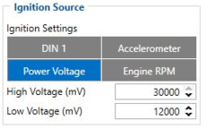
Ignition Source:
- 101 - Eventual settings (1 - DIN 1, 2 - Accelerometer, 4 - Power Voltage, 8 - Engine RPM).
- 104 - Hight Voltage ( MIN - 0, MAX - 30000).
- 105 - Low Voltage ( MIN - 0, MAX - 29999).
Quick start: From default configuration to Fleet Maintenance Schedules in one SMS:
" setparam 11800:1;11801:0;101:4;104:30000;105:12000"
Note: Before SMS text, two space symbols should be inserted if no SMS username or password was set in SMS \ Call settings.
After configuration device start parameters now we go to configure OBD II elements.
In the photo below (this is example case) you see where you must go to configurate main parameter that you need to have from device.
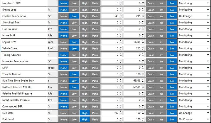
In OBD II window you see a lot of I/O elements to configure the device properly you will need to know which parameters can be read from the vehicle using our OBD trackers. To know what parameters can be read please visit How to check available OBDII data.
Parsing Fleet Maintenance Schedule records
1.Prerequisites:
1.1. Open TCP/UDP port
1.2. Go to Java parser first start guide
2.Parsing example:
| Unparsed received data in hexadecimal stream |
|---|
| 00000000000004d608130000017738b113a8000efcea74209c63c200b60096050010000c05ef01f0011505c800
450105b50008b600074230fB6c430f3d44006b02f10000601a1000038753000 000017738b1241790000efceb6e 209c63d05b50008b600074230 ff430f3d44006b020000601a100003875300002900017738b11f600001f0011505 |
| AVL Data Packet Part | HEX Code Part |
|---|---|
| Zero Bytes | 00 00 00 00 |
| Data Field Length | 00 00 04 d6 |
| Codec ID | 08 (Codec 8) |
| Number of Data 1 (Number of Total Records) | 13 |
| Timestamp | 00 00 01 77 38 b1 13 a8 (Mon Jan 25 08:37:46 UTC 2021) |
| Priority | 00 |
| Longitude | 00 01 77 38 |
| Latitude | b1 13 a8 00 |
| Altitude | 0e fc |
| Angle | ea 74 |
| Satellites | 20 |
| Speed | 9c 63 |
| N of Total ID | 12 |
| N1 of One Byte IO | 09 |
| 1’st IO ID | EF (AVL ID: 239, Name: Ignition) |
| 1’st IO Value | 01 |
| 2’nd IO ID | F0 (AVL ID: 240, Name: Movement) |
| 2’nd IO Value | 01 |
| 3’rd IO ID | 15 (AVL ID: 21, Name: GSM Signal) |
| 3’rd IO Value | 05 |
| 4'th IO ID | 50 (AVL ID: 200, Name: Sleep Mode) |
| 4'th IO Value | 00 |
| 5'th IO ID | 45 (AVL ID: 69, Name: GNSS Status) |
| 5'th IO Value | 01 |
| N2 of Two Byte IO | 5 |
| 1’st IO ID | B5 (AVL ID: 181, Name: GNSS PDOP) |
| 1’st IO Value | 8 |
| 2’nd IO ID | B6 (AVL ID: 32, Name: Coolant Temperature) |
| 2’nd IO Value | 61 |
| 3’rd IO ID | 42 (AVL ID: 66, Name: External Voltage) |
| 3’rd IO Value | 30 FC |
| 4'th IO ID | 43 (AVL ID: 67,Name: Battery Voltage) |
| 4'th IO Value | 0F 3D |
| 5'th IO ID | 24 (AVL ID: 36, Name: Engine RPM) |
| 5'th IO Value | 06 A2 |
| N4 of Four Byte IO | 02 |
| 1'st IO ID | 29 (AVL ID: 41, Name: Throttle Position) |
| 1’st IO Value | 5E |
| 2’nd IO ID | (AVL ID: 16, Name: Total Odometer) |
| 2’nd IO Value | 03 87 53 |
| CRC-16 | 00 00 73 2E |
In platform
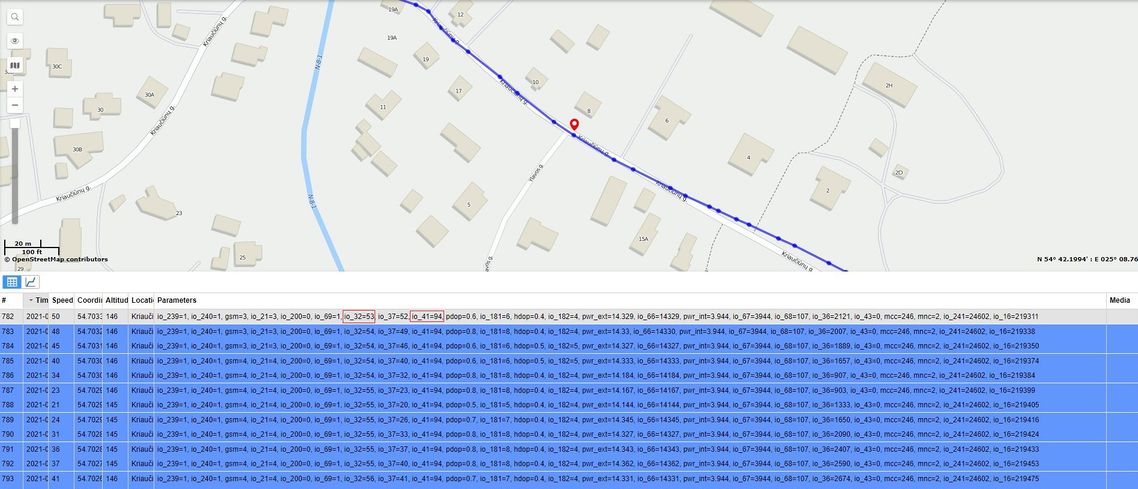
TAVL: Open TAVL → select client → select Street Map → select device → choose the date from which to which to show the records → push advanced → push show button and then you will see in left down corner all information.
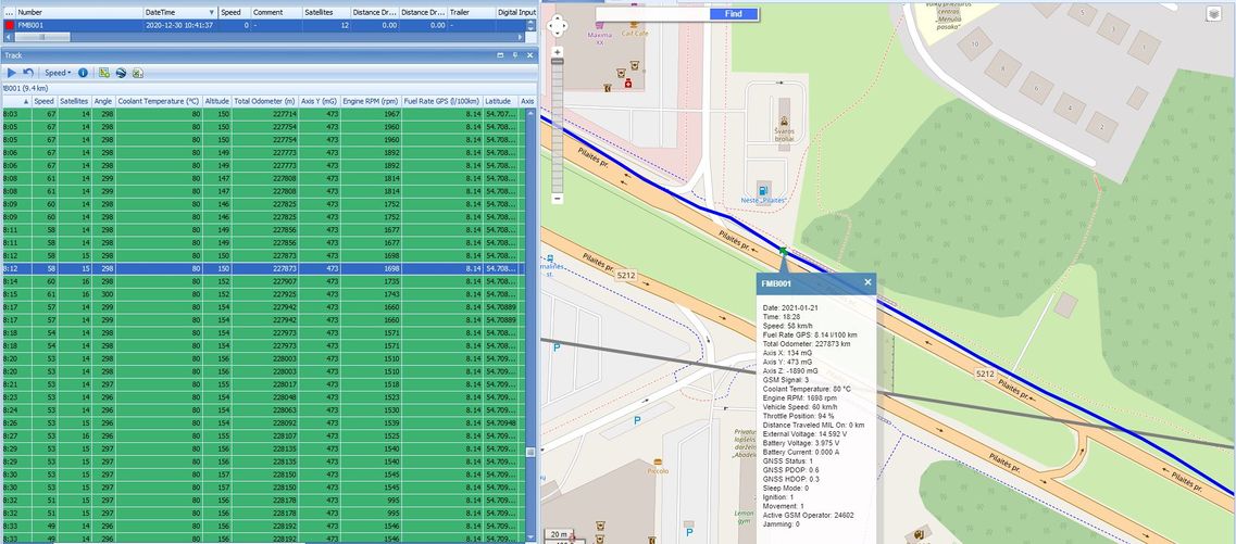
WIALON: Open WIALON → open messages → push unit ( select your device) → choose the date from which to which to show the records → select message (data messages) → push execute button and you will see all information.
