Analog Fuel Sensor
Analog Fuel Sensor Connection

General procedure of connection and calibration for an analogue
FLS (fuel level sensor)
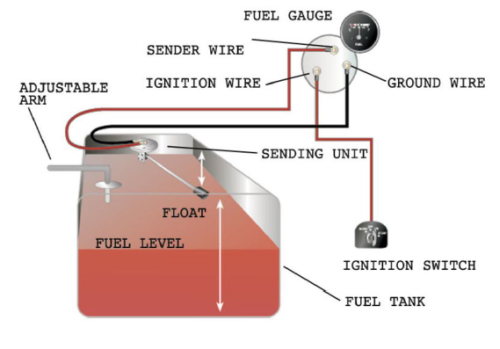
Find the fuel sender wire:
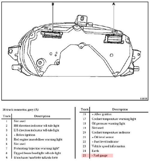
- Easiest way to find fuel sending wire is to consult a car service manual or wiring diagram for the instrument panel. A lot of them can be found online by searching for "<your car model> service manual". The exact pin and wire can usually be found without having to test everything.
- Fuel sending wire will have variable voltage based on how much fuel the sensor is detecting. Without any manuals, fuel sending wire can be detected by measuring changes in voltage after filling/emptying fuel tank. Sensors can go from LOW voltage = FULL; HIGH voltage = EMPTY, or in reverse. The ranges can also vary, so there’s no way to know beforehand what voltage is supposed to be full and what voltage is supposed to be empty.

Typically, the fuel sending wire will come from a multiple wire connector along with all the other dashboard inputs.
- With no manual, wires coming from the fuel gauge have to be tested by measuring their current, then reducing the amount of fuel in the fuel tank and then measuring current again. The wire that has reduced current in response to less fuel is the fuel sender wire. All the wires have to be measured between each change in fuel level. The fuel sending wire is typically red or pink, but this is not guaranteed to be true
- A more direct way of finding the fuel sending wire is to take out fuel sensor from the fuel tank and move the floating arm from full to empty while measuring the current of the wires. This should be done with electronics on and without ignition (key in ACC position). Fuel tank should also be empty for safety reasons, and trying to turn ignition on in this situation is likely to damage internal components.
Connecting and calibrating

- When you have found the fuel sending wire, simply connect the tracker to the wire using the Analog Input (AIN) wire from the device.
- After the tracker is connected, it must then be calibrated.
- Empty the gas tank.
- Use the Teltonika Configurator Status window, Maintenance tab where calibration table (with liters and voltage).
- Insert 0 liters, start engine, wait for around 30sec to sensor to find the equivalent voltage.
- Afterwards press the refresh button. Voltage will be filled in automatically. Continue by filling in around 5-10% more of fuel tank with the engine off. Turn the engine on and wait around 30sec.
- More measurements would provide more accurate readings later on. You can track voltage in Status > I/O tab to see how it fluctuates at any given moment.
