Difference between revisions of "FTC881 First Start"
From Wiki Knowledge Base | Teltonika GPS
| Line 45: | Line 45: | ||
* Locate the battery in your vehicle. If present remove the battery cover to access the battery. | * Locate the battery in your vehicle. If present remove the battery cover to access the battery. | ||
| − | * There is a double sided tape on the back of the device, use it to attach the device on the battery, so that the GNSS antenna and LEDs indicators are facing up. | + | * There is a double sided tape on the back of the device, use it to attach the device on the battery, so that the GNSS antenna |
| − | + | and LEDs indicators are facing up. | |
| − | |||
| − | |||
| − | |||
| − | |||
| − | |||
| − | |||
'''CONNECTING POWER SOURCE''' | '''CONNECTING POWER SOURCE''' | ||
| − | * | + | * Device power wire is designed to be directly connected to the positive terminal fastener of the vehicle battery. |
| − | |||
| − | |||
| − | |||
'''CONNECTING GROUND WIRE''' | '''CONNECTING GROUND WIRE''' | ||
| − | * | + | * Device ground wire is designed to be directly connected to the negative terminal fastener of the vehicle battery. |
| − | |||
| − | |||
[[Category:FTC881]] | [[Category:FTC881]] | ||
Revision as of 16:46, 18 April 2024
Main Page > Fast & Easy Trackers > FTC881 > FTC881 First StartSmall and smart waterproof tracker
HOW TO INSERT MICRO-SIM CARD AND CONNECT THE BATTERY
- Gently remove FTC881 cover using plastic pry tool from one side.
- Gently remove FTC881 cover using plastic pry tool from another side.
- Insert Nano-SIM card as shown. Make sure that Nano-SIM card cut-off corner is pointing forward to slot.
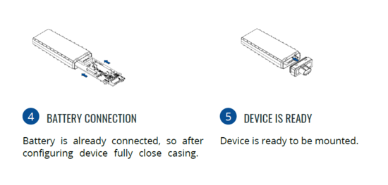
- Connect the battery as shown on device. Make sure that "+" is pointing to SIM-slot, "-" is pointing to GNSS antenna.
- Attach device cover back. Device is ready to be connected.
 |
Nano-SIM card insertion/removal must be performed when device is powered off – external voltage and internal battery disconnected. Otherwise Nano-SIM card might be damaged or device will not detect it. |
PC CONNECTION (WINDOWS)
- Power- up FTC881 with DC voltage (10-90V) power supply using power wires. LEDs should start blinking, see “LED behaviour description”.
- Connect device to computer using USB Type-C cable and install USB driver, see "HOW TO INSTALL USB DRIVERS (WINDOWS)".
HOW TO INSTALL USB DRIVERS (WINDOWS)
- Please download COM port drivers from here.
- Extract and run TeltonikaCOMDriver.exe.
- Click Next in driver installation window.
- In the following window click Install button.
- Setup will continue installing the driver and eventually the confirmation window will appear. Click Finish to complete the setup.
CONFIGURATION (WINDOWS)
At first FTC881 device will have default factory settings set. These settings should be changed according to the user's needs. Main configuration can be performed via Teltonika Configurator tool (TCT).
MOUNTING RECOMMENDATIONS
DEVICE FASTENING
- Locate the battery in your vehicle. If present remove the battery cover to access the battery.
- There is a double sided tape on the back of the device, use it to attach the device on the battery, so that the GNSS antenna
and LEDs indicators are facing up.
CONNECTING POWER SOURCE
- Device power wire is designed to be directly connected to the positive terminal fastener of the vehicle battery.
CONNECTING GROUND WIRE
- Device ground wire is designed to be directly connected to the negative terminal fastener of the vehicle battery.


