Difference between revisions of "FTC921 General description"
From Wiki Knowledge Base | Teltonika GPS
(→PINOUT) |
(→PINOUT) |
||
| Line 22: | Line 22: | ||
|- | |- | ||
| style="border: 1px solid white; border-bottom: 2px solid #E8E8E8; text-align: left; vertical-align: center; background: white;" | 3 | | style="border: 1px solid white; border-bottom: 2px solid #E8E8E8; text-align: left; vertical-align: center; background: white;" | 3 | ||
| − | | style="border: 1px solid white; border-bottom: 2px solid #E8E8E8; text-align: left; vertical-align: center; background: white;" | <span style=color:#FFEF00>''' | + | | style="border: 1px solid white; border-bottom: 2px solid #E8E8E8; text-align: left; vertical-align: center; background: white;" | <span style=color:#FFEF00>'''DIN1'''</span> |
| style="border: 1px solid white; border-bottom: 2px solid #E8E8E8; text-align: left; vertical-align: center; background: white;" | (Yellow) Digital input, channel 1. DEDICATED FOR IGNITION INPUT. | | style="border: 1px solid white; border-bottom: 2px solid #E8E8E8; text-align: left; vertical-align: center; background: white;" | (Yellow) Digital input, channel 1. DEDICATED FOR IGNITION INPUT. | ||
|- | |- | ||
| style="border: 1px solid white; border-bottom: 2px solid #E8E8E8; text-align: left; vertical-align: center; background: white;" | 4 | | style="border: 1px solid white; border-bottom: 2px solid #E8E8E8; text-align: left; vertical-align: center; background: white;" | 4 | ||
| − | | style="border: 1px solid white; border-bottom: 2px solid #E8E8E8; text-align: left; vertical-align: center; background: white;" | <span style=color:#3B3B3B>''' | + | | style="border: 1px solid white; border-bottom: 2px solid #E8E8E8; text-align: left; vertical-align: center; background: white;" | <span style=color:#3B3B3B>'''AIN1'''</span> |
| style="border: 1px solid white; border-bottom: 2px solid #E8E8E8; text-align: left; vertical-align: center; background: white;" | (Grey) Analog input, channel 1. Input range: 0-90 V DC. | | style="border: 1px solid white; border-bottom: 2px solid #E8E8E8; text-align: left; vertical-align: center; background: white;" | (Grey) Analog input, channel 1. Input range: 0-90 V DC. | ||
|- | |- | ||
Latest revision as of 15:08, 15 December 2023
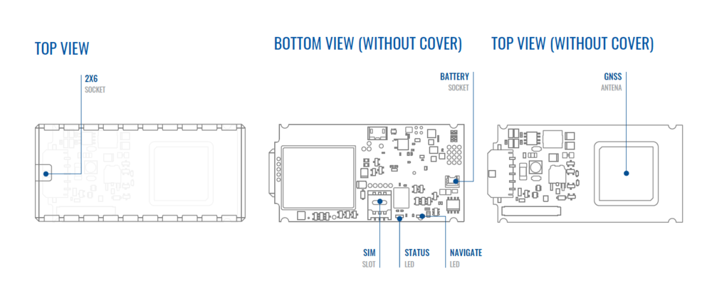
Main Page > Basic Trackers > FTC921 > FTC921 Manual > FTC921 General descriptionKNOW YOUR DEVICE
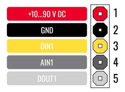
PINOUT
| PIN NUMBER | PIN NAME |
DESCRIPTION |
|
|---|---|---|---|
| 1 | VCC | (Red) Power supply (+10-90 V DC) (+). | |
| 2 | GND | (Black) Ground (-). | |
| 3 | DIN1 | (Yellow) Digital input, channel 1. DEDICATED FOR IGNITION INPUT. | |
| 4 | AIN1 | (Grey) Analog input, channel 1. Input range: 0-90 V DC. | |
| 5 | DOUT1 | (White) Digital output. Open collector output. Max. 0,5 A DC. |

