FTC961 General description
From Wiki Knowledge Base | Teltonika GPS
Main Page > Basic Trackers > FTC961 > FTC961 Manual > FTC961 General description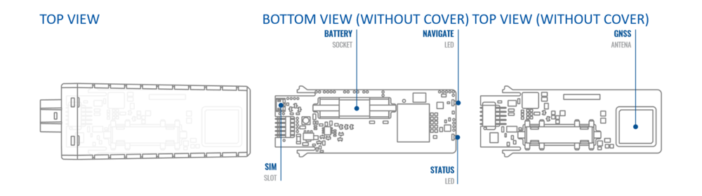
KNOW YOUR DEVICE

PINOUT
| PIN NUMBER | PIN NAME |
DESCRIPTION |
 |
|---|---|---|---|
| 1 | VCC | (Red) Power supply (+10-90 V DC) (+). | |
| 2 | GND | (Black) Ground (-). | |
| 3 | DIN1 | (Yellow) Digital input, channel 1. DEDICATED FOR IGNITION INPUT. | |
| 4 | AIN1 | (Grey) Analog input, channel 1. Input range: 0-90 V DC. | |
| 5 | DOUT1 | (White) Digital Output. Open collector output. Max. 0,5 A DC. |

