Anti-Theft Solution and Stolen Vehicle Recovery
Disclaimer

If you are not using Bluetooth®, please consider turning it off or change Bluetooth® PIN to remove potential risks.
If you are using Bluetooth® we strongly recommend using AES encryption for enhanced security.
Solution description
Vehicle theft is one of the world’s fastest-growing crimes as thieves turn to use highly advanced equipment, e.g. jammers. By jamming GSM signals, the criminals aim to interfere and inhibit the performance of a tracking device – its ability to monitor and gather important information. Luckily, Teltonika trackers have a functionality that can detect jamming and help to prevent theft or to recover a stolen vehicle.
We are glad that you decide to test our “Anti-Theft and stolen vehicle recovery” solution.
Here you will find how to prepare and test this solution.
What you need for a solution?
- The anti-theft solution is supported by FMBxyz series (including FMB640), FMUxyz, FMCxyz and FMMxyz Teltonika devices, which have DOUT which in this scenario is used to connect a buzzer or use starter cut-off relay.
- The SIM card in order to get data to your server
- Relay, which will be controlled by DOUT may turn on the alarm, disable engine start, or lock doors. Please contact your sales representative to order the relay from Teltonika. If you want to use your own relay please double-check the type of relay and its supported voltage range. FMB platform configurator, to configure the device in order to work with this solution.
- FOTA WEB to remotely send the configuration to the device.
Installation
It’s important to well hide the tracker, so it would not be a simple task for the thieves to find and unplug it. But also, please do not forget to follow mounting recommendations as well.
Although devices have high gain antennas it’s important to mount devices with stickers on top and in metal-free space. The device should be firmly fixed to the surface or cables. Please make sure, that device is not fixed to heat emitting or moving parts.
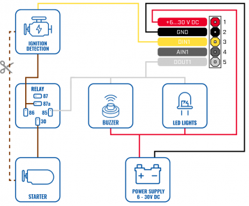
To have a working solution it’s important to properly make wiring.
As the main solution accessory is a relay, please make sure that the right contacts are connected
During installation please follow recommendations in order to avoid damaging device and vehicle:
- Wires should be connected while the module is not plugged in.
- Be sure that after the car computer falls asleep, power is still available on the chosen wire. Depending on the car, this may happen in a 5 to 30 minutes period.
- When the module is connected, be sure to measure the voltage again if it did not decrease.
- The ground wire is connected to the vehicle frame or metal parts that are fixed to the frame.
Configuration
1. Prerequisites:
1.1. Read through First start guide
1.2. Understanding of possible Sleep modes.
2. Configuring Jamming scenario
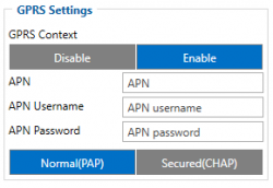
Parameter ID – Parameter name GPRS settings:
- 2001 – APN
- 2002 – APN username (if there are no APN username, empty field should be left)
- 2003 – APN password (if there are no APN password, empty field should be left)
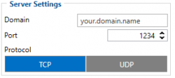
Server settings:
- 2004 – Domain
- 2005 – Port
- 2006 – Data sending protocol (0 – TCP, 1 – UDP)
After successful GPRS/SERVER settings configuration, device will synchronize time and update records to the configured server. Time intervals and default I/O elements can be changed by using Teltonika Configurator or SMS parameters.
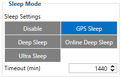
Sleep settings:
- 102 – Sleep settings(0 – Disable, 1 – Gps sleep, 2 – Deep sleep, 3 – Online Deep sleep, 4 – Ultra sleep)
- Note: This scenario will not work with Deep Sleep and Ultra Deep Sleep modes, since they disable the device's GSM module to save power.
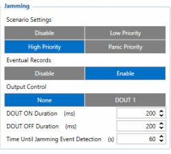
Jamming scenario settings:
- 11300 – Scenario priority
- 11303 – Eventual settings (0 – Disable, 1 – Enable)
- 11304 – Output Control (0 – None, 1 – DOUT1, 2 – DOUT2, 3 – DOUT3)
- 11301 – DOUT ON Duration (ms)
- 11302– DOUT OFF Duration (ms)
- 11305 – Time Until Jamming Event Detection (s)
Note: It's not recommended to set 11305 parameter to a very value(few seconds) because jamming scenario might be triggered while driving in the city.
Quickstart: From default configuration to Jamming detection in one SMS:
" setparam 2001:APN;2002:APN_username;2003:APN_password;2004:Domain;2005:Port;2006:0;102:1;11300:2;11304:1"
This SMS will set up your device to report the Jamming Detection scenario to the server and toggle ON DOUT1 during jamming.
Note: Before SMS text, two space symbols should be inserted if no SMS username or password was set in SMS \ Call settings.
Parsing information
1.Prerequisites:
1.1. Open TCP/UDP port
1.2. Go to Java parser first start guide
2. Parsing example:
| Unparsed received data in hexadecimal stream |
|---|
| 000000000000004608010000017501DAF828010F0E4792209AC4FB00C200D70C0000F90D06EF01F00
01503C8004501F900B50005B6000342334D43000044000002F10000601A100000000000010000732E |
| AVL Data Packet | |
|---|---|
| AVL Data Packet Part | HEX Code Part |
| Zero Bytes | 00 00 00 00 |
| Data Field Length | 00 00 00 D6 |
| Codec ID | 08 (Codec 8) |
| Number of Data 1 (Number of Total Records) | 01 |
| Timestamp | 00 00 01 75 01 DA F8 28 (Wed Oct 07 06:58:49 UTC 2020) |
| Priority | 01 |
| Longitude | 0F 0E 47 92 |
| Latitude | 20 9A C4 FB |
| Altitude | 00 C2 |
| Angle | 00 D7 |
| Satellites | 0C |
| Speed | 00 00 |
| Event IO ID | F9 (AVL ID: 249, Name: Jamming) |
| N of Total ID | 0D |
| N1 of One Byte IO | 06 |
| 1’st IO ID | EF (AVL ID: 239, Name: Ignition) |
| 1’st IO Value | 01 |
| 2’nd IO ID | F0 (AVL ID: 240, Name: Movement) |
| 2’nd IO Value | 00 |
| 3’rd IO ID | 15 (AVL ID: 21, Name: GSM Signal) |
| 3’rd IO Value | 03 |
| 4'th IO ID | C8 (AVL ID: 200, Name: Sleep Mode) |
| 4'th IO Value | 00 |
| 5'th IO ID | 45 (AVL ID: 69, Name: GNSS Status) |
| 5'th IO Value | 01 |
| 6'th IO ID | F9 (AVL ID: 249, Name: Jamming) |
| 6'th IO Value | 00 (0 – jamming stop, 1 – jamming start) |
| N1 of Two Byte IO | 05 |
| 1’st IO ID | B5 (AVL ID: 181, Name: GNSS PDOP) |
| 1’st IO Value | 00 05 |
| 2’nd IO ID | B6 (AVL ID: 182, Name: GNSS HDOP) |
| 2’nd IO Value | 00 03 |
| 3’rd IO ID | 42 (AVL ID: 66, Name: External Voltage) |
| 3’rd IO Value | 33 4D |
| 4'th IO ID | 43 (AVL ID: 67, Name: Battery Voltage) |
| 4'th IO Value | 00 00 |
| 5'th IO ID | 44 (AVL ID: 68, Name: Battery Current) |
| 5'th IO Value | 00 00 |
| N4 of Four Bytes IO | 02 |
| 1’st IO ID | F1 (AVL ID: 241, Name: Active GSM Operator) |
| 1’st IO Value | 00 00 60 1A |
| 2’nd IO ID | 10 (AVL ID: 16, Name: Total Odometer) |
| 2’nd IO Value | 00 00 00 00 |
| N8 of Eight Bytes IO | 00 |
| Number of Data 2 (Number of Total Records) | 01 |
| CRC-16 | 00 00 73 2E |
Demonstration in platform
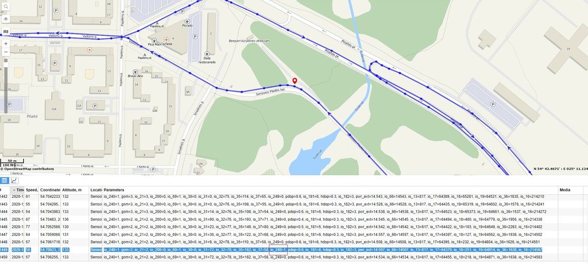
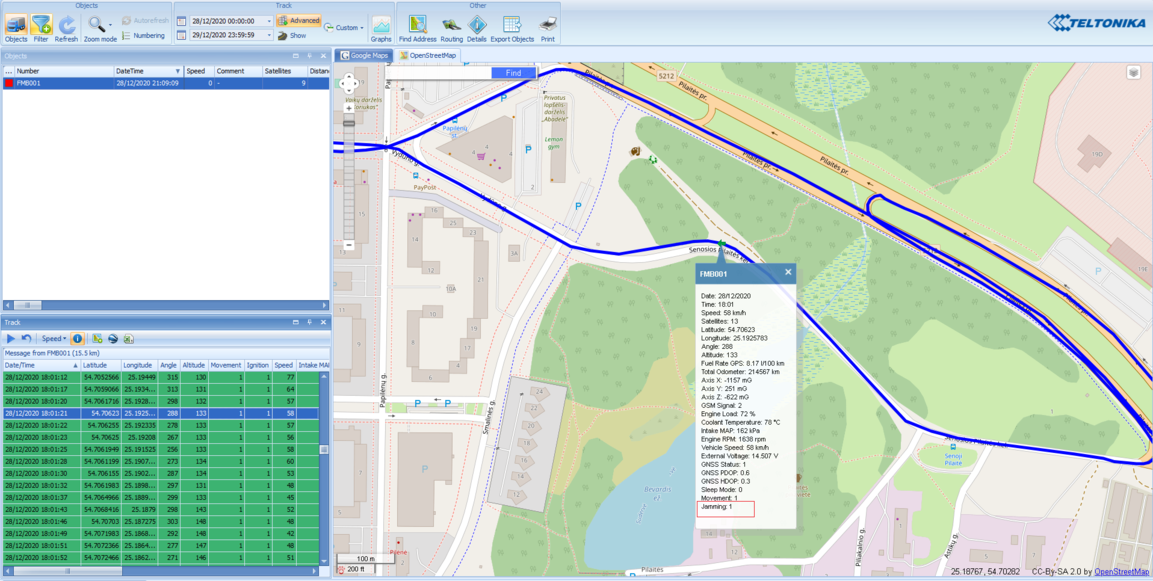
TAVL: Open TAVL → select client → select Street Map → select device → choose the date from which to show the records → push advanced → push show button and then you will see in left down corner all information.
WIALON: Open WIALON → open messages → push unit ( select your device) → choose the date from which to show the records → select message (data messages) → push execute button and you will see all information.
