FMB110 General description
Main Page > Advanced Trackers > FMB110 > FMB110 Manual > FMB110 General description
FMB110 is a tracking terminal with GNSS and GSM connectivity, which is able to collect device coordinates and transfer them via GSM network to a server. This device is perfectly suitable for applications, which require the location acquirement of remote objects.
Package contents
The FMB110 device is supplied to the customer in a cardboard box containing all the equipment that is necessary for operation. The package contains:
- FMB110 device;
- Input and output power supply cable with 2x6 connection pins;
- Micro USB cable;
Basic characteristics
GSM / GPRS / GNSS features:
- Teltonika TM2500 quad band module (GSM 850 / 900 / 1800 / 1900 MHz);
- GPRS Multi-Slot class 12 (Up to 240 kbps);
- SMS (text, data);
- Integrated GNSS receiver;
- Up to -165 dBm GNSS receiver sensitivity.
Hardware features:
- Built-in movement sensor;
- Built-in Bluetooth® 4.0 LE;
- Internal High Gain GNSS antenna;
- Internal High Gain GSM antenna;
- Internal flash memory 128MB (422 400 Records);
Interface features:
- Power supply: +10...+30 V;
- 2 digital inputs;
- 1 analog input;
- 1 configurable input DIN3 or AIN2;
- 2 open collector digital outputs (connecting external relays, LED, buzzers etc);
- 1-Wire temperature sensor;
- 1-Wire iButton;
- LVCAN RX (INPUT 5);
- LVCAN TX (INPUT 6);
- 2 LEDs indicating device status.
Special features:
- Fast position fix (Outdoor areas);
- High Quality track even in high density urban canyon;
- Ultra small case;
- Ready for harsh environment;
- Easy to mount in limited access areas;
- Firmly fasten;
- 2 LED status indication;
- Real time tracking;
- Smart data acquisition based on:
- Time;
- Speed;
- Angle;
- Distance;
- Ignition or any other I/O event;
- Sending acquired data via GPRS;
- GPRS and SMS I/O events;
- Virtual odometer;
- Jamming detection;
- Configurable using Secured SMS Commands;
- 1x micro SIM card; 1x eSIM;
- Overvoltage protection;
| Description | Voltage | Duration |
|---|---|---|
| Normal operation |
+10 ... +30 V |
Unlimited |
| Protection turns on, device turns off | 34 V | Unlimited |
| Maximum voltage | < 70 V | Unlimited |
| Maximum voltage impulse | 90 V | 5 ms |
Technical features
| Part name | Physical specification |
|---|---|
| Navigation indication | LED |
| Modem indication | LED |
| Socket | Soldered inner socket |
| USB | Micro USB socket |
| GNSS | Internal GNSS antenna |
| GSM | Internal GSM antenna |
| Technical details | |
|---|---|
| 2 W max. Current consumption at 12 V (Power supply 6...30 V DC) |
GPRS: average 69.15 mA Nominal: average 35.23 mA GNSS sleep: average 19.72 mA Deep Sleep: average 7.35 mA Online Deep Sleep: average 10.96 mA Ultra Deep Sleep: average 5.69 mA |
| Operating temperature | -40..+85 °C |
| Storage temperature | -40..+70 °C |
| Storage relative humidity | 5..95% (no condensation) |
| Device + case + battery weight | 50 g |
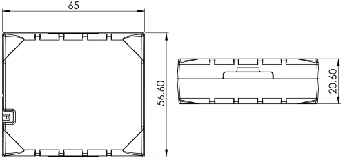
Dimension drawing:

Electrical characteristics
| Characteristic description | Value | |||
|---|---|---|---|---|
| Min. | Typ. | Max. | Unit | |
| Supply Voltage: | ||||
| Supply Voltage (Recommended Operating Conditions) |
+10 | +30 | V | |
| Digital Output (Open Drain grade): | ||||
| Drain current (Digital Output OFF) | 120 | µA | ||
| Drain current (Digital Output ON, Recommended Operating Conditions) |
0.1 | 0.5 | A | |
| Static Drain-Source resistance (Digital Output ON) |
400 | 600 | mΩ | |
| Digital Input: | ||||
| Input resistance (DIN1) | 47 | kΩ | ||
| Input resistance (DIN2) | 51.7 | kΩ | ||
| Input resistance (DIN3) | 47 | kΩ | ||
| Input voltage (Recommended Operating Conditions) |
0 | Supply voltage | V | |
| Input Voltage threshold (DIN1) | 7.5 | V | ||
| Input Voltage threshold (DIN2) | 2.5 | V | ||
| Input Voltage threshold (DIN3) | 2.5 | V | ||
| Analog Input: | ||||
| Input voltage (Recommended Operating Conditions), Range 1 |
0 | +10 | V | |
| Input resistance, Range 1 | 150 | kΩ | ||
| Measurement error on 12V, Range 1 | 3 | % | ||
| Additional error on 12 V, Range 1 | 360 | mV | ||
| Measurement error on 30 V, Range 1 | 3 | % | ||
| Additional error on 30 V, Range 1 | 900 | mV | ||
| Input Voltage (Recommended Operating Conditions), Range 2 |
0 | +30 | V | |
| Input resistance, Range 2 | 150 | kΩ | ||
| Measurement error on 12V, Range 2 | 3 | % | ||
| Additional error on 12 V, Range 2 | 360 | mV | ||
| Measurement error on 30 V, Range 2 | 3 | % | ||
| Additional error on 30 V, Range 2 | 900 | mV | ||
| Output Supply Voltage 1-Wire: | ||||
| Supply voltage | +4.5 | +4.7 | V | |
| Output inner resistance | 7 | Ω | ||
| Output current (Uout > 3.0 V) | 30 | mA | ||
| Short circuit current (Uout = 0) | 75 | mA | ||
 |
Analog Input error margin can increase if temperature varies. |
Absolute maximum ratings
| Characteristic description | Value | |||
|---|---|---|---|---|
| Min. | Typ. | Max. | Unit | |
| Supply Voltage (Absolute Maximum Ratings) |
-32 | +32 | V | |
| Drain-Source clamp threshold voltage (Absolute Maximum Ratings), (Idrain = 2 mA) |
+36 | V | ||
| Digital Input Voltage (Absolute Maximum Ratings) |
-32 | +32 | V | |
| Analog Input Voltage (Absolute Maximum Ratings) |
-32 | +32 | V | |