FTC305 First Start
Small 4G LTE (CAT 1) tracker for e-bikes, e-scooters and e-forklifts with CAN interface and 10-97 V power supply range
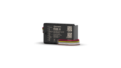
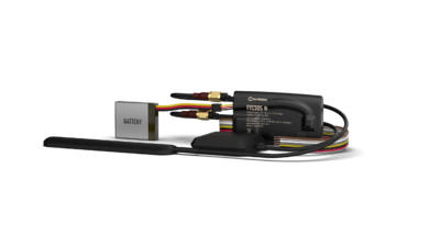
KNOW YOUR DEVICE
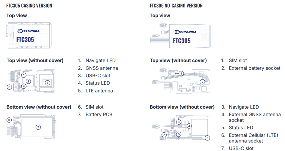
SET UP YOUR DEVICE
| |
Physical SIM card insertion/removal must be performed when device is powered off – external voltage disconnected. Otherwise, the SIM card might be damaged or device will not detect it. |
FTC305 CASING VERSION
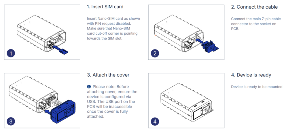
FTC305 NO-CASING VERSION
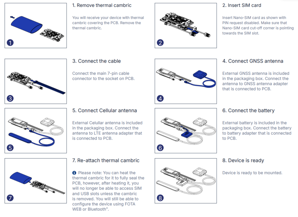
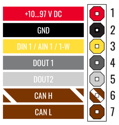
PINOUT
PC CONNECTION (WINDOWS)
- Connect device to computer using USB Type-C cable.
Please note: FTC305 device does not require an external power supply for configuration. However, without external power, data sending and other cellular connectivity functions will not work. If you want to test the device on a table, it is advised to power up FTC305 with a DC voltage (10-97V) power supply using power wires. - Install USB driver, see "HOW TO INSTALL USB DRIVERS (WINDOWS)".
HOW TO INSTALL USB DRIVERS (WINDOWS)
- Please download COM port drivers from here.
- Extract and run TeltonikaCOMDriver.exe.
- Click Next in driver installation window.
- In the following window click Install button.
- Setup will continue installing the driver and eventually the confirmation window will appear. Click Finish to complete the setup.
CONFIGURATION (WINDOWS)
Most Teltonika devices are shipped with default factory settings. Use Telematics Configuration Tool (TCT) to change these settings according to your needs.
| TCT | |
|---|---|
| Operating system | Windows 10 Windows 11 |
| MS .NET Framework version | MS .NET framework 6.0 |
| Version | 64 bit |
| Disk Storage | 1 GB of free disk space |
| Internet | Ethernet port or Wi-Fi w/ network access for auto-update |
TCT
- Download the TCT (compressed archive).
- Extract the archive and launch the executable. The TCT will be installed.
- Launch the TCT.
- In the Discovered devices list, select your device and press Configure.
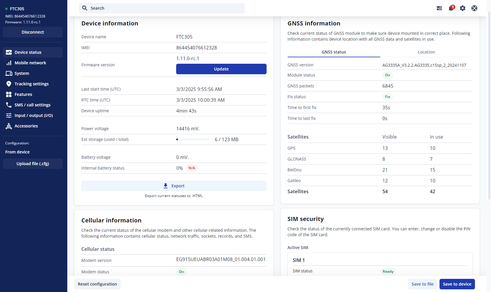
- The Device status window opens. It contains device, GNSS and Cellular information.
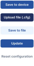
Save to device – saves configuration to device.
Upload file – loads configuration from file.
Save to file – saves configuration to file.
Update – update device firmware.
Reset configuration – sets device configuration to default.
Most important configuration sections are Mobile network (Server, Mobile network settings) and Tracking settings (data collection parameters). More details about FTC305 configuration using TCT can be found here.
QUICK SMS CONFIGURATION
The default configuration ensures best track quality and optimal data usage.
Quickly set up your device by sending this SMS command to it:
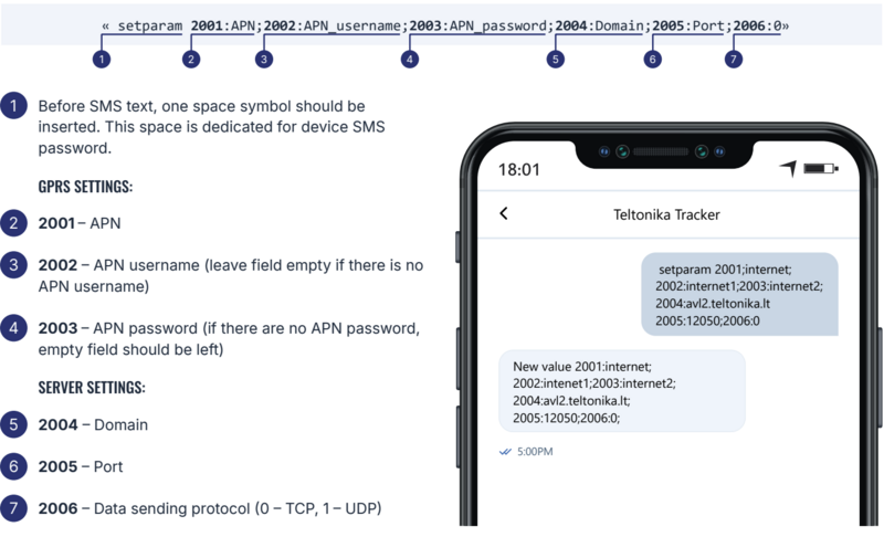
DEFAULT CONFIGURATION SETTINGS
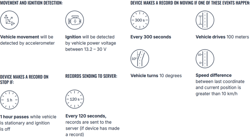
After successful SMS configuration, FTC305 device will synchronize time and update records to configured server. Time intervals and default I/O elements can be changed by using TCT or Parameter list.
MOUNTING RECOMMENDATIONS
CONNECTING WIRES
- Wires should be fastened to the other wires or nonmoving parts. Do not place the wires near moving or heat-emitting objects.
- All electrical connections must be properly isolated. No bare wires should be visible. Re-apply isolation to wires if you removed factory isolation during installation.
- If the wires are placed in the exterior or in places where they can be damaged or exposed to heat, humidity, dirt, etc., additional isolation should be applied.
CONNECTING POWER SOURCE
- Ensure that after the vehicle computer falls asleep, power is still available on chosen wire. Depending on vehicle, this may happen in 5 to 30 minutes period.
- When module is connected, measure voltage again to make sure it did not decrease.
- It is recommended to connect main power cable to the main battery of the vehicle.
CONNECTING IGNITION WIRE
- Make sure that you have selected the correct wire for ignition signal - the electrical signal from the wire should be present after starting the engine.
- Check if this is not an ACC wire (when key is in the first position, most of the vehicle electronics are ON).
- Check if power is still available when you turn off any of vehicles devices.
- Ignition is connected to the ignition relay output. As alternative, any other relay, which has power output when ignition is on, may be chosen.
CONNECTING GROUND WIRE
- Ground wire must be connected to the vehicle frame or metal parts that are fixed to the frame.
- If the wire is fixed with the bolt, the loop must be connected to the end of the wire.
- For better contact scrub paint from the spot where loop is going to be connected.
LED INDICATIONS
This section is an explanation of LED indications on FTC305 device.
NAVIGATION LED INDICATIONS
| Behaviour | Meaning |
|---|---|
| Blinking every second | GNSS module is working, GNSS fix is acquired (normal operation) |
| Permanently switched on | GNSS module is working, but fix is not acquired (no position) |
| Off | GNSS module is off because: (a) the device is not working or (b) the device is in sleep mode |
STATUS LED INDICATIONS
| Behaviour | Meaning |
|---|---|
| Blinking every second | Device is working, GPRS session is active (normal operation) |
| On | Device is working, no active GPRS sessions |
| Off | Device is not working |
BASIC CHARACTERISTICS
| Module | |
|---|---|
| Name | FTC305-QJAB0: Quectel EG915U-EU, internal antennas, casing version FTC305-QKAB0: Quectel EG915U-LA, internal antennas, casing version FTC305-QJXB0: Quectel EG915U-EU, external antennas, external battery, no casing version FTC305-QKXB0: Quectel EG915U-LA, external antennas, external battery, no casing version |
| Technology | LTE CAT 1/GSM/GPRS/GNSS |
| GNSS | |
| GNSS | GPS, GLONASS, GALILEO, BEIDOU |
| Receiver | L1: 75 channel |
| Tracking sensitivity | -165 dBm |
| Position Accuracy | < 1.8 m CEP |
| Velocity Accuracy | < 0.1 m/s (within +/- 15% error) |
| Hot start | < 1 s |
| Warm start | < 25 s |
| Cellular | |
| 2G bands | GSM: B2/B3/B5/B8 |
| 4G bands | FTC305-QJAB0: LTE FDD (EG915U-EU): B1/B3/B5/B7/B8/B20/B28 FTC305-QJXB0: LTE FDD (EG915U-EU): B1/B3/B5/B7/B8/B20/B28 FTC305-QKAB0: LTE FDD (EG915U-LA): B2/B3/B4/B5/B7/B8/B28/B66 FTC305-QKXB0: LTE FDD (EG915U-LA): B2/B3/B4/B5/B7/B8/B28/B66 |
| Data transfer | LTE FDD (CAT 1): Max. 10 Mbps (DL) / Max. 5 Mbps (UL) GSM (GPRS): Max. 85.6 Kbps (DL) / Max. 85.6 Kbps (UL) |
| Transmit power | Class 4 for GSM900: 33 dBM ± 2dB Class 1 for DCS1800: 30 dBm ± 2 dB Class 3 for LTE-FDD: 23 dBm ± 2 dB |
| Data support | SMS (TEXT, PDU), Network protocols (TCP, UDP) |
| Power | |
| Input voltage range | 10 - 97 V DC |
| Back-up battery | Casing version: 380 mAh Li-ion battery 3.7V (1.41 Wh) No casing version: 1200 mAh Li-ion battery 3.7 V (4.44 Wh) (External) |
| Internal fuse | 3A |
| Power Consumption | At 12V < 40 mA (Nominal with no load) At 12V < 0.25 A Max (with full Load/Peak) |
| Bluetooth® Technology | |
| Specification | 5.3 + LE |
| Interface | |
| Digital Inputs | 1 |
| Digital Outputs | 2 |
| Analog Inputs | 1 |
| 1-Wire | 1 |
| CAN | 1 |
| GNSS antenna | Casing version: Internal High Gain No casing version: External (SMA female connector) |
| GSM antenna | Casing version: Internal High Gain No casing version: External (RP SMA female connector) |
| USB | 2.0 USB Type-C |
| LED indication | 2 status LED lights |
| SIM | Nano-SIM |
| Memory | 128MB internal flash memory |
| Physical Specification | |
| Dimensions | Casing version: 69 x 41 x 20.9 mm (L x W x H) No casing version: 62 x 39.6 x 11.5 mm (L x W x H)
|
| Weight | Casing version: 76.8 g No casing version (with accessories): 126.1 g |
| Operating Environment | |
| Operating temperature | -30 °C to +85 °C |
| Storage temperature | -30 °C to +85 °C |
| Operating humidity | 65 ± 20% non-condensing |
| Ingress protection rating | Casing version: IP67 No casing version: N/A |
| Battery charge temperature | 0 °C to +45 °C |
| Battery discharge temperature | -20 °C to +60 °C |
| Battery storage conditions | Casing version: -10 °C to +25 °C for 3 or more months No casing version: -20 °C to +45 °C for 3 or more months |
| Data Codec | |
| Codec support | Codec 8 Extended |
| Features | |
| Sensors | Accelerometer |
| Scenarios | Crash detection, Over Speeding detection, Trip, Odometer, Eco driving, Excessive idling, Network Jamming detection, Unplug detection, Auto Geofence, Towing detection, Fall down detection, Static navigation, Ignition ON counter, Custom scenarios, Manual CAN data reading, Manual CAN commands |
| Sleep modes | Power Saving settings |
| Configuration and firmware update | FOTA WEB, Telematics Configuration Tool (TCT) |
| Time Synchronization | GNSS, NTP, NITZ |
| Ignition detection | Digital Input 1, Accelerometer, External Power Voltage |
ELECTRICAL CHARACTERISTICS
| Characteristic description | Value | |||
|---|---|---|---|---|
| Min. | Typ. | Max. | Unit | |
| Supply Voltage | +10 | +97 | V | |
| Supply Protection Voltage (Absolute Maximum Ratings, Reverse/Forward Polarity) |
-100 | +100 | V | |
| Digital Input 1 Voltage (DIN state 0->1) |
+2.5 | +100 | V | |
| Analog Input 1 Voltage | 0 | +100 | V | |
| Digital Output 1/2 Voltage | 0 | +100 | V | |
| Digital Input 1 Current (At 100V Input) |
0.7 | mA | ||
| Analog Input 1 Current (At 100V Input) |
0.7 | mA | ||
| Digital Output 1/2 Current | 0 | 500 | mA | |
| Digital Output 1/2 Overcurrent Threshold | 800 | mA | ||


