GH5200 Bluetooth® 4.0 settings
Disclaimer

If you are not using Bluetooth®, please consider turning it off or change Bluetooth® PIN to remove potential risks.
If you are using Bluetooth® we strongly recommend using AES encryption for enhanced security.
Bluetooth® 4.0 settings
GH5200 offers Bluetooth® 4.0 (Bluetooth® Low Energy, also referred as BLE) functionality.
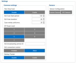
Configurable parameters:
- Non Stop Scan - Enabled Non Stop Scan feature, the device will try to scan for the sensors all the time if any of them are configured.
- BLE Scan Start period - Device will start BLE scanning at each period. Not used if ‘Non Stop Scan’ is enabled.
- BLE Scan Duration - At each scan period start, device will scan for BLE Scan duration. Not used if ‘Non Stop Scan’ is enabled.
- Scan retries until error - Configured scan retries, to show the Error Value '3000' - sensor disconnected.
- BT Power Level' - Higher level will allow device to be seen at a longer distance, but will increase power usage.
- BLE broadcasting service ID - This service ID will be placed into device’s advertising message. Needs to be specified, in order to start broadcasting.
- BLE connection control - Allows other devices to connect via BLE.
- Backup Tracker - Enables Backup Tracker feature.
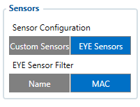
- Sensor Configuration – Custom Sensor - Bluetooth® connection mode. Disabled: Bluetooth® 4.0 connection will not be used. TZ-BT04/05/05B sensor: this Bluetooth® connection will be used to communicate with TZ-BT04/05/05B sensor. Advanced - It allows to gather data from BLE device‘s broadcast packets regardless of what data packing protocol is used. EYE Sensor - allows to read EYE Sensor data by Name or MAC address.
Configuration modes
Non Stop Scan Enabled.
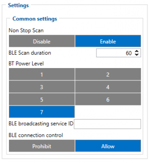
In Configurator when Non Stop sensor scans is active update frequency & scan retries until error will be hidden. Although BLE scan duration will still be active because it is important for btgetlist SMS command.
Non Stop Scan Disabled, Scan period is selected manually.
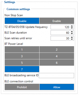
From the picture above, the Scan time period will be selected from two sources, BLE Scan Duration - the time when sensors are scanned and the Update frequency - The time when the sensor information is packed as the AVL Data record.
For example:
Update frequency - 120 seconds.
BLE Scan Duration - 60 Seconds
Device will start the first scan after 120 seconds and will scan nearby BLE devices for 60 seconds to update configured sensor data. The sensor data will be updated every 120 seconds. Update Frequency is counted even while a scan is performed.
Update frequency period passes. 120 seconds -> 0 seconds, a 60 second scan is initiated. Update Frequency countdown is restarted (countdown from configured value to 0) while the scan (according to the BLE Scan duration parameter) is performed.
Advanced Mode
When Advanced mode is selected a table with configurable parameters will appear:
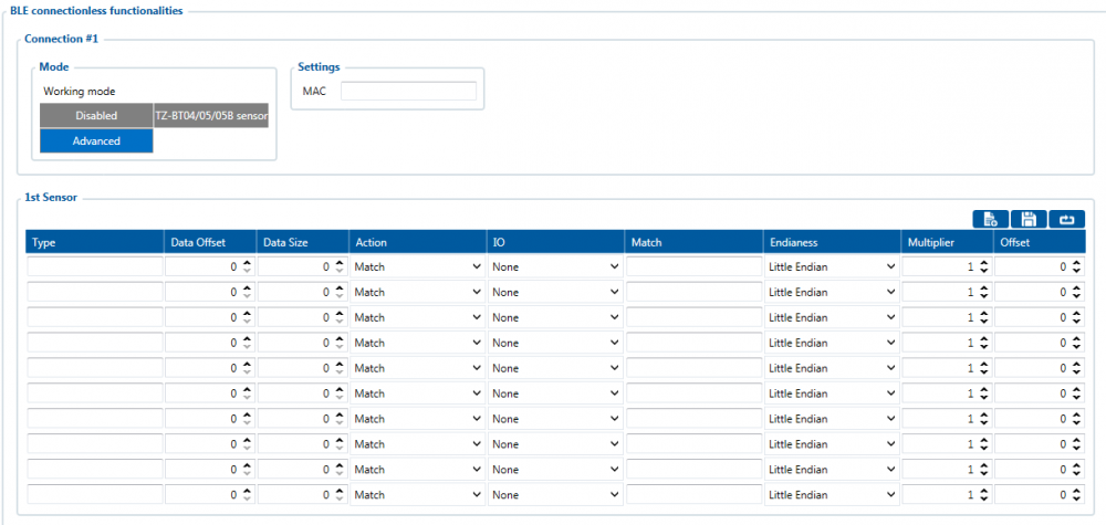
- The table has 9 types of parameters:
- Type – EIR data type. This parameter will indicate which type to look for and work with. Note: We have also added type with value 0xFE which will indicate to work with a whole data packet and not just a single data type.
- Data Offset – start index of data we are interested in.
- Data Size – size of the data we are interested in.
- Action – two actions are possible: Match and Save. Match means that we want to perform a validation of certain data. Save means that we want to get certain data and later save it to an AVL record.
- IO – tells which IO element's data will be saved to. Used only with Save action.
- Match – hex string to be matched with BLE sensor data. Used only with Match action.
- Endianness – endianness of data: little endian (ex. 0x1122) or big endian (ex. 0x2211). Used only with Save action.
- Multiplier – value to be used to multiply output data. Used only with Save action.
- Offset – value to be added to output data. Used only with Save action.
EYE Sensors
Note: Feature only available from firmware version 55.02.03.Rev.02 and later.
For this feature to work BLE Devices need to be selected under Beacon List - Beacon Detection.
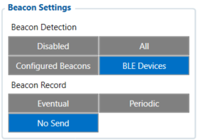
When EYE Sensors is selected, Eye Sensor connectionless functionalities or EYE list search window will appear, depending on the selected EYE Sensor filter.
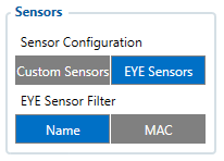
Name
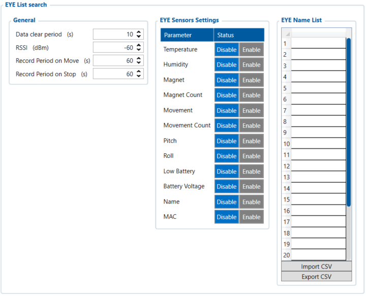
When EYE Sensors Filter is set to Name, the Eye List search window will appear on the configurator. With this setting, separate EYE Sensor records (AVL ID: 11317) will be generated according to the configured parameters, which are described below:
- Data Clear period- defines how long the FM tracker waits when the Eye sensor is not detected before removing it from the Eye Sensor list and not sending the sensor values. If Data Clear Period is set to 0, then the EYE Sensor will not be removed from the EYE Sensor list and it will always be included in the periodic records.
- RSSI- Parameter defines the dBm threshold value of when the EYE sensor will be added to the sensor list. If the FM tracker detects the RSSI lower than the configured value, it will not be added to the EYE Sensor list.
- Record period - Defines how often the EYE Sensor record (AVL ID: 11317) will be generated when tracker is operating On Stop or On Move modes.
- EYE Sensor Settings - Define what sensor readings data is included in to the EYE Sensor Records. Sensor readings which are not needed can be disabled, to reduce data consumption.
- EYE Name list - Defines what EYE sensors will be added to EYE Sensor list. For EYE Sensors to be added to the list, only the beginning part of the EYE Sensor local name has to match. For example, if in the EYE name list “EYE_SENSOR” is added and the FM tracker detects EYE_SENSOR1, EYE_SENSOR2, EYE_SENSORXYZ, all these EYE Sensors will be added to EYE Sensor list. If the EYE name list is left empty, all the detected EYE Sensors will be included in the EYE Sensor list. NOTE: If EYE Sensor has a name that matches configured one in EYE Name List and if it has a MAC address, that matches configured one in EYE Sensors filtered by MAC address, then such sensor will not be added to EYE Sensor list, but it’s data will be added according EYE Sensor filtered by MAC IO elements.
Once Eye Sensor filtering by name list is selected, EYE Sensor records containing the AVL ID:11317 will start being generated. Below is an example of how EYE Sensor data is packed into AVL ID 11317
AVL ID 11317 structure
| Eye Sensor #1 | |
|---|---|
| EYE Sensor #1 Data length | 1 byte |
| 1st Parameter ID | 1 byte |
| 1st Parameter Data Length | 1 byte |
| 1st Parameter Data | variable |
| 2nd Parameter ID | 1 byte |
| 2nd Parameter Data Length | 1 byte |
| 2nd Parameter Data | variable |
| <...> | |
| Nth Parameter ID | 1 byte |
| Nth Parameter Data Length | 1 byte |
| Nth Parameter Data | variable |
| Eye Sensor #2 | |
| Eye Sensor #2 Data length | 1 byte |
| 1st Parameter ID | 1 byte |
| 1st Parameter Data Length | 1 byte |
| 1st Parameter Data | variable |
| 2nd Parameter ID | 1 byte |
| 2nd Parameter Data Length | 1 byte |
| 2nd Parameter Data | variable |
| <...> | |
| Nth Parameter ID | 1 byte |
| Nth Parameter Data Length | 1 byte |
| Nth Parameter Data | variable |
| Eye Sensor #N | |
| ... | ... |
Parameter IDs are used to identify what type of EYE Sensor information is included in the packet. Below is the table describing the possible EYE Sensor parameter IDs, along with their data type and data length.
| Parameter ID | Name | Data type | Description |
|---|---|---|---|
| 5 | Eye Sensor Device Name | Array | Device’s name from Device Name List tab |
| 6 | EYE Sensor Temperature | 2 byte signed integer | Temperature value measured by EYE Sensor from List Values from -32768 to +32768 with 0.01 C delta |
| 7 | EYE Sensor Humidity | 1 byte unsigned integer | Humidity measured by EYE Sensor from List Values from 0 to 100% |
| 8 | EYE Sensor Magnet presence | 1 byte unsigned integer | Magnet measured by EYE Sensor from List Values from 0 to1 |
| 9 | EYE Sensor Movement presence | 1 byte unsigned integer | Movement measured by Eye Sensor from List Values |
| 10 | EYE Sensor Movement count | 2 byte unsigned integer | Movement counts measured by EYE Sensor from List Values |
| 11 | EYE Sensor Pitch | 1 byte signed integer | Pitch angle measured by Eye Sensor from list Values |
| 12 | EYE Sensor Angle Roll | 2 byte signed integer | Roll Angle measured by EYE Sensor from List Values |
| 13 | EYE Sensor Low battery indicator | 1 byte unsigned integer | Low battery state measured by EYE Sensor from List Values from 0 to1 |
| 14 | EYE Sensor Battery voltage | 2 byte unsigned integer | Low battery state measured by EYE Sensor from List Values from 0 to1 |
| 15 | EYE Sensor MAC adress | 6 byte unsigned integer | Device's MAC adress |
| 16 | EYE Sensor Magnet trigger count* | 2 byte unsigned integer | Magnet trigger counts measured by EYE Sensor from List Values
*Only available with evaluation firmware BTSX.1.2.8.magcounter.R.0 of EYE Devices |
MAC
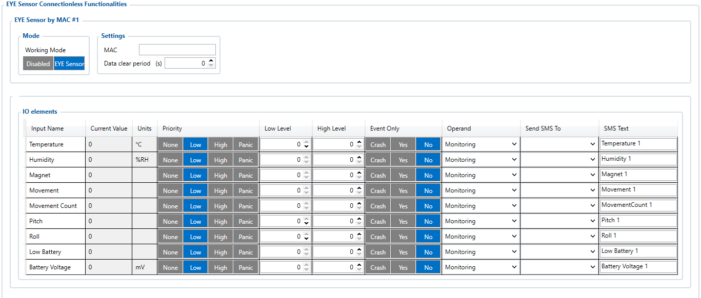
IF EYE Sensors are selected to be filtered by MAC address, separate EYE sensor records will not be generated; EYE sensor values will be included into regular records with their corresponding IO elements. Up to 4 EYE Sensors can be configured with different MAC Addresses.
In the case of filtering by MAC Address, more advanced configuration is possible, as EYE Sensors’ IOs’ Low, High level, Event Only and Operand parameters can also be configured separately for each IO.
- Working Mode - parameter has 2 options – Disabled and EYE Sensor. When it is disabled, EYE Sensor IO values will not be included into the records. When EYE Sensor is selected, EYE Sensor IO values will be included into records.
- MAC Settings - parameter specifies the MAC address of the EYE Sensor for the FM tracker to read, parse its data and put to corresponding IO elements. If the sensor is not found for set amount of scan retries, error values will be stored into IO elements.
- I/O elements - allows for advanced EYE sensor I/O elements configuration.
Table below describes I/O elements which were added for EYE sensor with the new functionalities release.
| Property ID in AVL packet | Property name | Bytes | Type | Min | Max | Multiplier | Units | Description |
|---|---|---|---|---|---|---|---|---|
| 11317 | EYE Sensor List | variable length | HEX | 0 bytes | 1024 bytes | - | - | EYE Sensor List |
| 10800 | EYE Temperature 1 | 2 | Signed | -32768 | 32768 | 0,01 | °C | Temperature measured by EYE sensor 1 |
| 10801 | EYE Temperature 2 | 2 | Signed | -32768 | 32768 | 0,01 | °C | Temperature measured by EYE sensor 2 |
| 10802 | EYE Temperature 3 | 2 | Signed | -32768 | 32768 | 0,01 | °C | Temperature measured by EYE sensor 3 |
| 10803 | EYE Temperature 4 | 2 | Signed | -32768 | 32768 | 0,01 | °C | Temperature measured by EYE sensor 4 |
| 10804 | EYE Humidity 1 | 1 | Unsigned | 0 | 100 | - | % | Humidity measured by EYE sensor 1 |
| 10805 | EYE Humidity 2 | 1 | Unsigned | 0 | 100 | - | % | Humidity measured by EYE sensor 2 |
| 10806 | EYE Humidity 3 | 1 | Unsigned | 0 | 100 | - | % | Humidity measured by EYE sensor 3 |
| 10807 | EYE Humidity 4 | 1 | Unsigned | 0 | 100 | - | % | Humidity measured by EYE sensor 4 |
| 10808 | EYE Magnet 1 | 1 | Unsigned | 0 | 1 | - | - | Magnet measured by EYE sensor 1 |
| 10809 | EYE Magnet 2 | 1 | Unsigned | 0 | 1 | - | - | Magnet measured by EYE sensor 2 |
| 10810 | EYE Magnet 3 | 1 | Unsigned | 0 | 1 | - | - | Magnet measured by EYE sensor 3 |
| 10811 | EYE Magnet 4 | 1 | Unsigned | 0 | 1 | - | - | Magnet measured by EYE sensor 4 |
| 10812 | EYE Movement 1 | 1 | Unsigned | 0 | 1 | - | - | Movement state and count measured by EYE sensor 1 |
| 10813 | EYE Movement 2 | 1 | Unsigned | 0 | 1 | - | - | Movement state and count measured by EYE sensor 2 |
| 10814 | EYE Movement 3 | 1 | Unsigned | 0 | 1 | - | - | Movement state and count measured by EYE sensor 3 |
| 10815 | EYE Movement 4 | 1 | Unsigned | 0 | 1 | - | - | Movement state and count measured by EYE sensor 4 |
| 10816 | EYE Pitch 1 | 1 | signed | -90 | 90 | - | - | Pitch and Roll angles measured by EYE sensor 1 |
| 10817 | EYE Pitch 2 | 1 | signed | -90 | 90 | - | - | Pitch and Roll angles measured by EYE sensor 2 |
| 10818 | EYE Pitch 3 | 1 | signed | -90 | 90 | - | - | Pitch and Roll angles measured by EYE sensor 3 |
| 10819 | EYE Pitch 4 | 1 | signed | -90 | 90 | - | - | Pitch and Roll angles measured by EYE sensor 4 |
| 10820 | EYE Low Battery 1 | 1 | Unsigned | 0 | 1 | - | - | Low Battery indication EYE sensor 1 |
| 10821 | EYE Low Battery 2 | 1 | Unsigned | 0 | 1 | - | - | Low Battery indication EYE sensor 2 |
| 10822 | EYE Low Battery 3 | 1 | Unsigned | 0 | 1 | - | - | Low Battery indication EYE sensor 3 |
| 10823 | EYE Low Battery 4 | 1 | Unsigned | 0 | 1 | - | - | Low Battery indication EYE sensor 4 |
| 10824 | EYE Battery Voltage 1 | 2 | Unsigned | 0 | 65535 | - | - | Battery Voltage of EYE sensor 1 |
| 10825 | EYE Battery Voltage 2 | 2 | Unsigned | 0 | 65535 | - | - | Battery Voltage of EYE sensor 2 |
| 10826 | EYE Battery Voltage 3 | 2 | Unsigned | 0 | 65535 | - | - | Battery Voltage of EYE sensor 3 |
| 10827 | EYE Battery Voltage 4 | 2 | Unsigned | 0 | 65535 | - | - | Battery Voltage of EYE sensor 4 |
| 10832 | EYE Roll 1 | 2 | signed | -180 | 180 | - | - | Roll value of EYE Sensor 1 |
| 10833 | EYE Roll 2 | 2 | signed | -180 | 180 | - | - | Roll value of EYE Sensor 2 |
| 10834 | EYE Roll 3 | 2 | signed | -180 | 180 | - | - | Roll value of EYE Sensor 3 |
| 10835 | EYE Roll 4 | 2 | signed | -180 | 180 | - | - | Roll value of EYE Sensor 4 |
| 10836 | EYE Movement Count 1 | 2 | unsigned | 0 | 65535 | - | - | Movement count value of EYE Sensor 1 |
| 10837 | EYE Movement Count 2 | 2 | unsigned | 0 | 65535 | - | - | Movement count value of EYE Sensor 2 |
| 10838 | EYE Movement Count 3 | 2 | unsigned | 0 | 65535 | - | - | Movement count value of EYE Sensor 3 |
| 10839 | EYE Movement Count 4 | 2 | unsigned | 0 | 65535 | - | - | Movement count value of EYE Sensor 4 |
Eye sensor parameters have error code values, which will written to the I/O value if parameter data is not received. From the error code value, it is possible to distinguish whether the issue is on the FM tracker side or the EYE Sensor. Below is a table describing these values.
| Parameter | Data length
(bytes) |
Data type | Error codes | Additional Notes | |
|---|---|---|---|---|---|
| Data Not Received by FM tracker | EYE Sensor indicates error | ||||
| Temperature | 2 | signed | 25000 | 25001 | |
| Humidity | 1 | unsigned | 250 | 251 | |
| Magnet | 1 | unsigned | 250 | 251 | |
| Magnet trigger count | 2 | unsigned | 65000 | 65001 | Only available with evaluation firmware BTSX.1.2.8.magcounter.R.0 of EYE Devices |
| Movement | 1 | unsigned | 250 | 251 | |
| Movement counter | 2 | unsigned | 65000 | 65001 | |
| Pitch | 1 | signed | 120 | 121 | |
| Roll | 2 | signed | 250 | 251 | |
| Low battery status | 1 | unsigned | 250 | 251 | |
| Battery voltage | 1 | unsigned | 250 | 251 | |
IO elements choices
| Name | Connection #1 AVL ID | Connection #2 AVL ID | Connection #3 AVL ID | Connection #4 AVL ID |
| None | - | - | - | - |
| Temperature | 25 | 26 | 27 | 28 |
| Battery | 29 | 20 | 22 | 23 |
| Humidity | 86 | 104 | 106 | 108 |
| Custom1 | 331 | 332 | 333 | 334 |
| Fuel | 270 | 273 | 276 | 279 |
| Luminosity | 335 | 336 | 337 | 338 |
| Fuel Frequency | 306 | 307 | 308 | 309 |
| Custom2 | 463 | 467 | 471 | 475 |
| Custom3 | 464 | 468 | 472 | 476 |
| Custom4 | 465 | 469 | 473 | 477 |
| Custom5 | 466 | 470 | 474 | 478 |
Backup Tracker
FMB devices from 03.28.06.Rev.02 firmware version have an ability to set up TAT100 device as a backup tracker. When the feature is enabled - FMB device starts to advertise encrypted BLE packets. In this solution - FMB device is a main tracker and TAT100 is set up as a backup tracker - TAT100 periodically checks if FMB advertised packets are available. If no FMB packets are read - an alarm is sent from TAT100 side and tracker switches it's mode to become the main tracker.
To enable Backup tracker:
1) BLE Connection control must be prohibited:
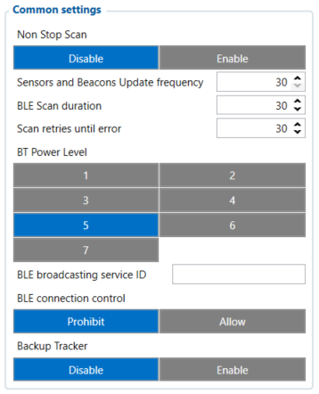
2) Enable Backup Tracker:
![]()
Note: when Backup Tracker is enabled - BLE sensor and Beacon settings become disabled. Additionally - Ultra Deep Sleep mode is also disabled (in this mode BLE packets would not be advertised)
TAT100 device recognizes the BLE packets by FMB devices IMEI, therefore after FMB configuration is done - additional TAT100 device configuration is required to support the full solution. You can learn more about the backup tracker and TAT100 configuration in our wiki site }}}

