Iridium Edge Configuration
Configuration
FMB Firmware implementation on FMC125/FMC225
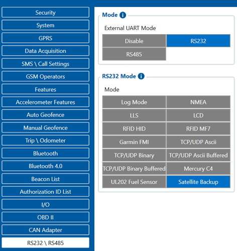
In order to enable Iridium support on FMB, first it is necessary to enable RS232 support and select “satellite backup” mode. This is available from FW 03.28.04.Rev.104
Correct configuration is shown in the picture below.

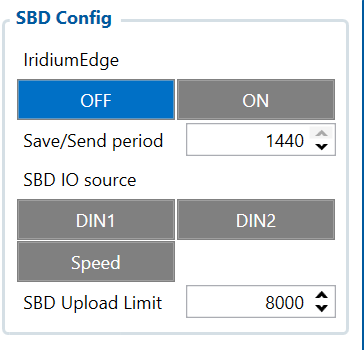
Next, there are a couple of configurable options. In the SBD config, IridiumEdge should be enabled and save/send period Set. This section can be found in the “Features” tab in the configurator.

Setting up Alarm priority records
NOTE: In addition, you can select which IO element can generate Alarm priority record. The configurable IO parameters are listed as SBD IO source in list above. In order to do that you need to configure these IO elements as Panic priority. If properly configured SBD records are generated and sent if there is no GSM connection.

In the scenario shown in the above picture when panic record is made (generated by Digital Input 1 or Digital Input 2) internal 90 seconds timer will start to tick and if in that timeout device will not send the record through GPRS network it will be sent with Iridium satellites.
SBD Upload Limit is configurable and resets every month. This option can ensure that no additional data is used so that no unexpected costs are experienced by the customer. Default value is 8000 (for 8KB plan). This option can be disabled by setting Upload limit to 0.
NOTE: SBD IO source functionality is still being implemented.
FMB Firmware configuration on FMX640/FMX641/FMX650 devices
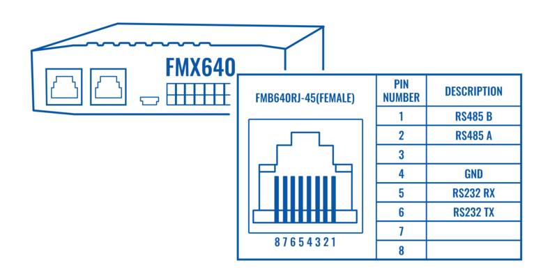
FMX640 can be setup with Iridium Edge by activating RS232 short burst data parameters, this is available from FW 01.02.18.Rev.00. It can be done visiting this tutorial Here.

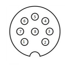
| PIN OUT Configuration | ||||
|---|---|---|---|---|
| Pin Number | Signal Name | Color | Signal Direction (With respect to iridium edge) | Description |
| 1 | Spare | White | - | Unused |
| 2 | Ground | Brown | Input | Signal and power GND |
| 3 | RS232_RX | Green | Input | RS232 input |
| 4 | RS232_TX | Yellow | Output | RS232 output |
| 5 | Power | Pink | Input | 9-32 V positive terminal |
| 6 | ON/OFF | Grey | Input | Optional line to power down Iridium edge |
| 7 | Network available | Blue | Output | - |
| 8 | Power detection | Red | Output | Active high when Iridium Edge is powered |
Important note: There is a noticeable difference in Iridium 8-pin cable layout from the standard version of the cable. We recommend purchasing a specific Iridium-made and certified 8-PIN cable directly from Teltonika. Please contact your administered sales representative to make an order.

