MSP500 Features settings
Eco/Green Driving
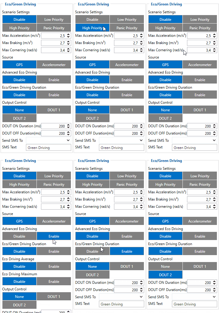
When vehicle parameters exceed the values of Max Acceleration, Max Braking or Max Cornering parameters, the scenario is activated: a record is generated and digital output status is changed to 1 when configured. You can configure all three parameters in m/s2 units. Scenario is activated until current Acceleration, Braking or Cornering value decreases below the set parameter value.
Parameters used with Eco/Green Driving functionality are given in a table below.
| Parameter name | Description |
|---|---|
| Scenario Settings | Enable/Disable Green driving functionality |
| Max Acceleration | Value which can be reached while accelerating without triggering harsh acceleration event. |
| Max Braking Acceleration | Value which can be reached while braking without triggering harsh braking event. |
| Max Cornering Acceleration | Value which can be reached while cornering without triggering harsh cornering event. |
| Source | Which source (GPS or accelerometer) data will be collected from. |
| Eco/Green Driving Duration | If enabled, additional record with Eco/Green Driving event duration (ms) will be saved and send to server. When GPS is selected as the data source duration accuracy will be in seconds. |
| Output Control | Which MSP500 Digital Output will be used for accesory (buzzer, LED and etc.) activation/deactivation. |
| DOUT ON Duration | A value in miliseconds (ms), for how long DOUT should be active. |
| DOUT OFF Duration | A value in miliseconds (ms), for how long DOUT should be inactive. |
Over Speeding
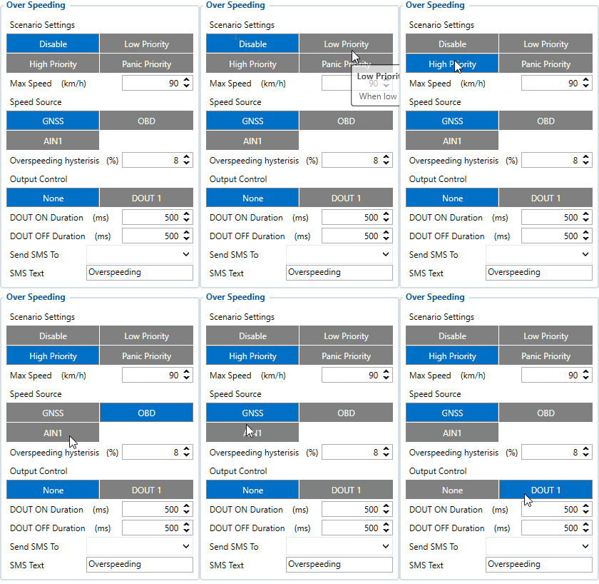
Over speeding scenario functionality has been modified for the MSP500 hardware.
Over speeding scenario supports multiple speed sources:
   * GNSS
   * OBDII (Bluetooth®)
   * Pulse counter input (vehicle speed sensor signal on AIN wire)
Speed source can be chosen in the configurator Features tab inside Over Speeding box.
Over speeding activates intermittent buzer sound when vehicles’ speed reaches 95% of set maximum speed to warn the driver.
If speed keeps increasing and reaches set maximum speed record is generated & output control may be started. Records are generated the same way as they are in the base over speeding functionality. If output control is enabled set output starts toggling in on and off time periods set in configurator “DOUT ON Duration” & “DOUT OFF Duration” fields. DOUT control and buzzer are canceled when vehicles’ speed decreases to below calculated speed value. This speed value is calculated using configured hysteresis percentage parameter which sets speed drop in percents regarding to set maximum speed (maximum speed value - hysteresis).
In this example maximum speed value is 80 km/h & hysteresis value is 28%. When actual speed reaches 76 km/h (80 km/h - (80 * 0,05)) buzzer is started. If speed is lowered buzzer stops. If speed keeps increasing set output is activated when max speed is reached. Relay control & buzzer are kept enabled until speed decreases to at least 57 km/h (80 km/h - (80 * 0,28)).
Jamming
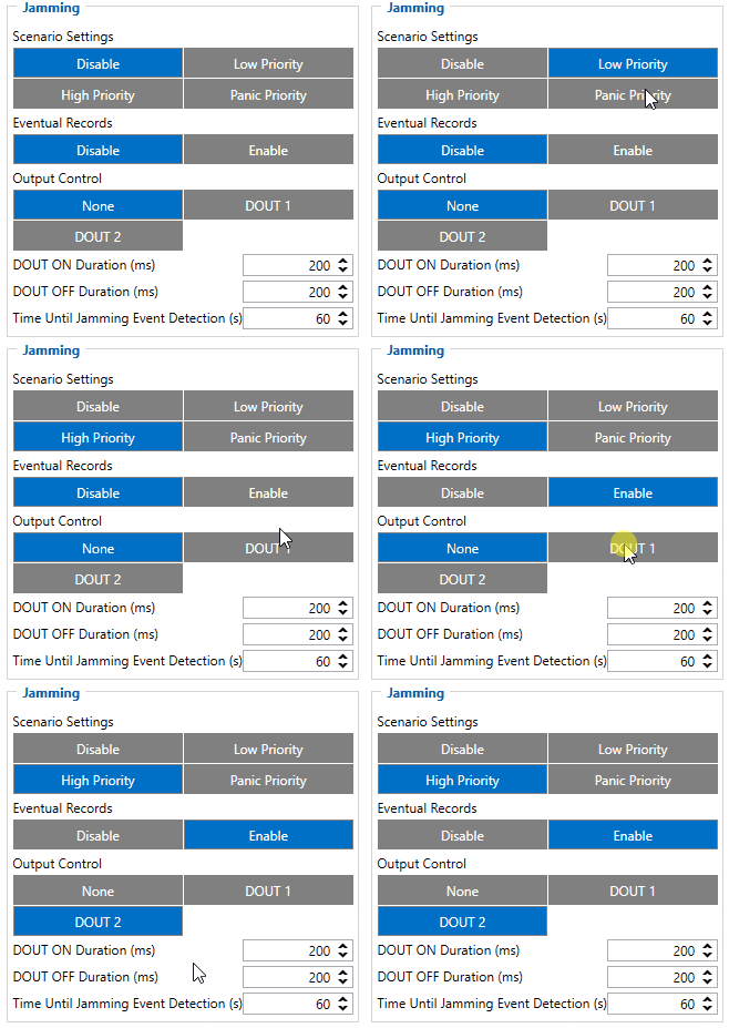
When a device detects GSM signal jamming, it activates the Jamming scenario. The device then starts a configurable timeout before responding that is intended to reduce false positives. After the timeout ends, the device generates an event record and digital output status is changed to 1 when configured If the device regains GSM signal before the countdown ends, no event will be generated and output will not be controlled. This Digital Output activation can be used to trigger measures to disrupt potential thieves using GSM signal jamming to steal your vehicle.
Connecting a Buzzer to the Digital Output to emit sounds as soon as jamming is detected is the most straightforward use of this scenario.
The Digital Output can be directly connected to the vehicle's alarm system to ensure the thief can not avoid triggering it.
It can also be connected to the central lock system to ensure that all the doors are locked.
A relay can be used to disable the starter motor. Usually used with the Immobilizer scenario.
Alternatively, the Digital output can also be connected to an LED visible to the driver to inform the driver when Jamming occurs.
Note that this scenario will not work with Deep Sleep, Ultra Deep Sleep and Online Deep Sleep modes, since they disable the device's GSM module to save power.
Eventual Records parameter can be configured: when it is disabled scenario status value will appear in each AVL record, otherwise, it will be appended only to eventual records.
For a more visual explanation, take a look at the video made by Teltonika explaining the use-case of Jamming Detection: Teltonika Jamming Detection scenario
DOUT Control Via Call
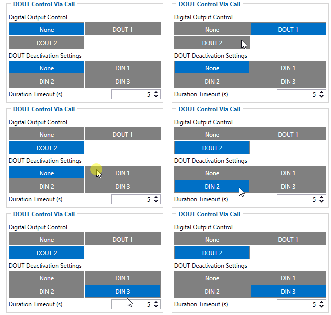
Scenario is activated and digital output is ON when call is received from a number which is on the authorized numbers list.
Call control functionality is following:
- When MSP500 is configured to control DOUT1/DOUT2 the device waits for an incoming call from a configured secure number. If a call is received MSP500 turns on DOUT1/DOUT2 for a user defined Duration Timeout. If duration timeout set to "0" DOUT1/DOUT2 will be OFF.
- DOUT1/DOUT2 can be turned off by Duration Timeout or by digital input 1, digital input 2 or digital input 3.
- DOUT1/DOUT2 will always be ON if, for example, DOUT deactivation is set to DIN1, but DIN1 will be never turned ON, or when duration timeout is set to maximum value (2147483647) which is about 68 years.
GNSS Fuel Counter
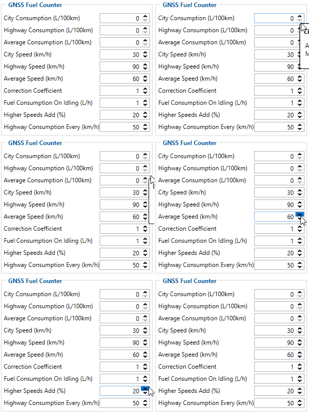
- To configure Fuel Counter parameters use fuel consumption norms which are presented in the technical documentation of the vehicle. By default speeds for these fuel consumption norms are: City – 30 km/h, Average - 60 km/h, Highway - 90 km/h. These values can be changed.
- When speed is higher than the highway fuel consumption speed, x% of highway fuel consumption is added every extra y km/h, by default MSP500 adds 20% every 50 km/h of extra speed. For example, the fuel consumption is (1.2 * (Highway Fuel Consumption)) at 140 km/h and (1.4 * (Highway Fuel Consumption)) at 190 km/h.
- Correction coefficient is used to correct every value of fuel consumption which is sent to the server through an expression of ((Used Fuel) * Correction coefficient). By default it is 1, with minimum and maximum values of accordingly 0.01 and 2. For example, when correction coefficient is 1 and MSP500 calculates that the amount of used fuel over 35 m distance is 20 ml, the value of 20 ml will be sent to the server, and if correction coefficient is 1.2, the value of 20 * 1.2 = 24 ml will be sent to the server.
- Fuel Consumption on Idling is used to calculate fuel consumption when the ignition is on, but the vehicle is stationary. The consumption value is 1 l/h by default, with a minimum and maximum of accordingly 0 and 5 l/h. This parameter is less than 1.0 l/h for almost all diesel cars and is equal to about 1.5 – 2.0 l/h for gasoline cars.
