Manual CAN Speed & Ignition source explained
Functionality description is based on latest firmware - 55.01.02.Rev.01.
Manual CAN Basic parameters purpose
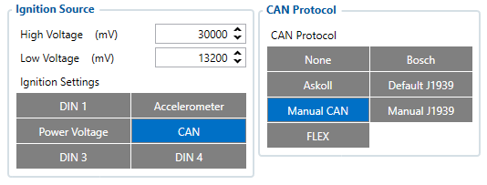
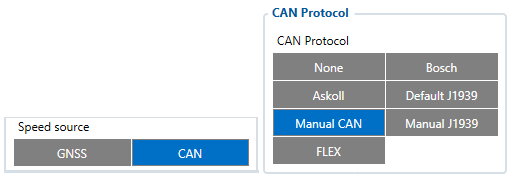
Manual CAN basic parameters can be used to detect Speed or Ignition, when Speed / Ignition sources are set to CAN in device's configuration.

Configuration explained for Ignition
Further configuration, to extract Ignition information from a CAN message is done under Manual CAN Settings section in configurator.
- Ignition Manual CAN Slot defines with which Manual CAN slot a CAN message containing information about Ignition will be captured.
- Ignition Data Mask defines which bits from incoming CAN message are responsible for ignition information. In other words - Ignition Data Mask parameter defines which data mask will be applied to received CAN data.
Ignition Data Mask parameter is 8 byte HEX value.
| Parameter Id | Name | Value | |
|---|---|---|---|
| Min | Max | ||
| 322 | Ignition Data Mask | 0000000000000000 | FFFFFFFFFFFFFFFF |
- Ignition Range Low defines lowest value limit to detect ignition (if ignition detection has several states)
| Parameter Id | Name | Value | ||
|---|---|---|---|---|
| Min | Max | Default | ||
| 323 | Ignition Range Low | 0 | 18446744073709551615 | 1 |
- Ignition Range High defines highest value limit to detect ignition (if ignition detection has several states)
| Parameter Id | Name | Value | ||
|---|---|---|---|---|
| Min | Max | Default | ||
| 324 | Ignition Range High | 0 | 18446744073709551615 | 1 |
Example:
Ignition information data value will be Received Data Value AND Data Mask.
Let's say that 7th byte of 8 bytes CAN message is responsible for ignition information, Received Data Value would be 0x1122334455667701.
Since only Ignition value is needed and it is located on 7th byte of previous CAN message, 00000000000000FF Data Mask should be applied.
In this case, incoming CAN message would hold only our masked ignition information - 0x0000000000000001.
Configuration explained for Speed
Further configuration, to extract Speed information from a CAN message is done under Manual CAN Settings section in configurator.
- Speed Manual CAN Slot defines with which Manual CAN slot a CAN message containing information about Speed will be captured.
- Speed Data Mask defines which bits from incoming CAN message are responsible for speed information. In other words - Speed Data Mask parameter defines which data mask will be applied to received CAN data.
Speed Data Mask parameter is 8 byte HEX value.
| Parameter Id | Name | Value | |
|---|---|---|---|
| Min | Max | ||
| 326 | Speed Data Mask | 0000000000000000 | FFFFFFFFFFFFFFFF |
- Speed Offset defines offset which will be substracted from calculated Speed value.
| Parameter Id | Name | Value | ||
|---|---|---|---|---|
| Min | Max | Default | ||
| 327 | Speed Offset | -2147483648 | 2147483647 | 0 |
- Speed Coefficient defines coefficient which raw CAN value will be multiplied with.
| Parameter Id | Name | Value | ||
|---|---|---|---|---|
| Min | Max | Default | ||
| 328 | Speed Coefficient | 0.0000001 | 1000000 | 1 |
Example:
Speed information data value will be Received Data Value AND Data Mask.
Let's say that 7th byte of 8 bytes CAN message is responsible for speed information, Received Data Value would be 0x1122334455667701.
Since only Speed value is needed and it is located on 7th byte of previous CAN message, 00000000000000FF Data Mask should be applied.
In this case, incoming CAN message would hold only our masked Speed information - 0x0000000000000001.


