Modbus slave integration with FMX125/FMX640
We can use the FMX125/FMX650 device‘s TCP - Binary feature to integrate the Modbus- RTU slave devices. If we can do some minor development on the server side, we can easily integrate all the Modbus-supported equipment like Generators, Energy Meters, Fuel level sensors, and Temperature & Humidity sensors, etc. without the additional cost of a Modbus controller and Router.
System Architecture
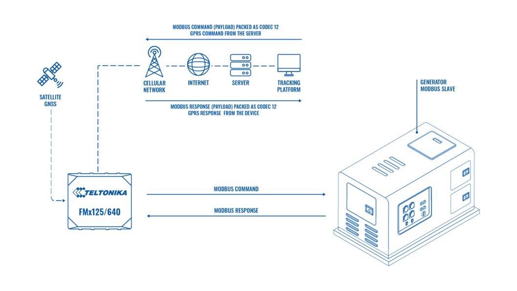
To implement this feature, we must properly implement the Teltonika codec 12 protocol in the server. In the device, we need to use TCP Binary mode. We need to primarily convert the Modbus commands to the Codec 12 GPRS commands and send them to the Teltonika device. The FM device (Teltonika device) will route these commands to the Modbus field device through RS232/RS485 serial interface. The response for the Modbus command from the field device will collect by the FM device, packed as a GPRS response, and will send to the server by using Codec 12 protocol. In the server, we need to decode this data according to the Modbus protocol.
The Modbus Protocol
What is Modbus?
Modbus is a serial communication protocol developed by Modicon and published by Modicon® in 1979 for use with its programmable logic controllers (PLCs). In simple terms, it is a method used for transmitting information over serial lines between electronic devices. The device requesting the information is called the Modbus Master and the devices supplying information are Modbus Slaves. In a standard Modbus network, there is one Master and up to 247 Slaves, each with a unique Slave Address from 1 to 247. The Master can also write information to the Slaves.
How does it work?
Modbus is transmitted over serial lines between devices. The simplest setup would be a single serial cable connecting the serial ports on two devices, a Master and a Slave. 
The data is sent as a series of ones and zeroes called bits. Each bit is sent as a voltage. Zeroes are sent as positive voltages and ones as negative. The bits are sent very quickly. A typical transmission speed is 9600 baud (bits per second).
How is data stored in Standard Modbus?
Information is stored in the Slave device at four different tables. Two tables store on/off discrete values (coils) and two store numerical values (registers). The coils and registers each have a read-only table and a read-write table. Each table has 9999 values. Each coil or contact is 1 bit and assigned a data address between 0000 and 270E. Each register is 1 word = 16 bits = 2 bytes and also has a data address between 0000 and 270E.
| Coil/Register Numbers | Data Addresses | Type | Table Name |
|---|---|---|---|
| 1-9999 | 0000 to 270E | READ-WRITE | Discrete Output Coils |
| 10001-19999 | 0000 to 270E | READ-ONLY | Discrete Input Contacts |
| 30001-39999 | 0000 to 270E | READ-ONLY | Analog Input Registers |
| 40001-49999 | 0000 to 270E | READ-WRITE | Analog Output Holding Registers |
Coil/Register Numbers can be thought of as location names since they do not appear in the actual messages. The Data Addresses are used in the messages. For example, the first Holding Register, number 40001, has the Data Address 0000. The difference between these two values is the offset. Each table has a different offset, which are 1, 10001, 30001, and 40001.
What is the Slave ID?
Each slave in a network is assigned a unique unit address from 1 to 247. When the master requests data, the first byte it sends is the Slave address. This way each slave knows after the first byte whether or not to ignore the message.
What is a function code?
The second byte sent by the Master is the Function code. This number tells the slave which table to access and whether to read from or write to the table.
| Function Code | Action | Table Name |
|---|---|---|
| 01 (01 HEX) | Read | Discrete Output Coils |
| 05 (05 HEX) | Write Single | Discrete Output Coil |
| 15 (0F HEX) | Write Multiple | Discrete Output Coils |
| 02 (02 HEX) | Read | Discrete Input Contacts |
| 04 (04 HEX) | Read | Analog Input Registers |
| 03 (03 HEX) | Read | Analog Output Holding Registers |
| 06 (06 HEX) | Write Single | Analog Output Holding Register |
| 16 (10 HEX) | Write Multiple | Analog Output Holding Registers |
Since most of the sensors and equipment are using holding registers, we will check the read holding registers function in detail.
Read Holding Registers (FC=03)
Request
This command is requesting the content of analog output holding registers # 40108 to 40110 from the slave device with address 17.
11 03 006B 0003 7687
11: The Slave Address (11 hex = address17)
03: The Function Code 3 (read Analog Output Holding Registers)
006B: The Data Address of the first register requested.(006B hex = 107, + 40001 offset = input #40108)
0003: The total number of registers requested. (Read 3 registers 40108 to 40110)
7687: The CRC (cyclic redundancy check) for error checking.
Response
11 03 06 AE41 5652 4340 49AD
11: The Slave Address (11 hex = address17)
03: The Function Code 3 (read Analog Output Holding Registers)
06: The number of data bytes to follow (3 registers x 2 bytes each = 6 bytes)
AE41: The contents of register 40108
5652: The contents of register 40109
4340: The contents of register 40110
49AD: The CRC (cyclic redundancy check).
What is a CRC?
CRC stands for Cyclic Redundancy check. It is two bytes added to the end of every Modbus message for error detection. Every byte in the message is used to calculate the CRC. The receiving device also calculates the CRC and compares it to the CRC from the sending device. If even one bit in the message is received incorrectly, the CRCs will be different, and an error will result.
TZONE TZ-THT02 RS485 Modbus RTU Temperature and Humidity sensor integration
We can integrate any Modbus slave device into our device including Generators, Energy Meters, Fuel level sensors, Flow meters, etc. In order to test the Modbus integration TZONE TZ-THT02 sensor shall be used.
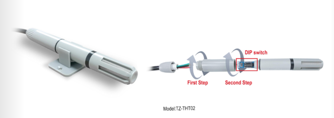
The THT-02 temperature and humidity sensor is designed based on the RS-485 communication interface, compatible with the standard Modbus-RTU protocol, and can be connected to the Modbus network to achieve temperature and humidity measurement and monitoring.
Sensor Technical Data
Supply voltage DC 5~24V
Current 5mA
RS-485 interface Transmission rate Optional 4800bps / 9600bps / 19200bps
Lead description
Yellow Green RS485 interface A+
Green RS485 interface B-
Black Ground (connect to the negative end of the power)
Red Power supply positive (connect to the positive end of the power supply)
DIP switch and address code
The above picture is a schematic diagram of the DIP switch. The DIP switch has 8 DIP positions. The corresponding numbers from 1 to 8 are 128, 64, 32, 16, 8, 4, 2, and 1, and these values are added together as the address code. As shown in the figure above, bits 1, 3, and 4 are in the ON position, so the address code is 128+32+16=176, that is, the address code is 176. We have set the sensor address as 1 by setting DIP switch 1 as ON.
Wiring scheme
Since the sensor supports the RS485, we need to use the RS485 interface of the FM device for the integration. Connect FM device RS485 – A to the sensor RS485 A and RS485 B to RS485 B of the sensor.
If we are using an RS232 Modbus device, we need to connect FM device Tx to Modbus device Rx and FM device Rx to Modbus device Tx.
If you are using FMX650, you need to use an RJ45 cable for connecting the RS232/RS485 devices.
FMX125/225 device configuration
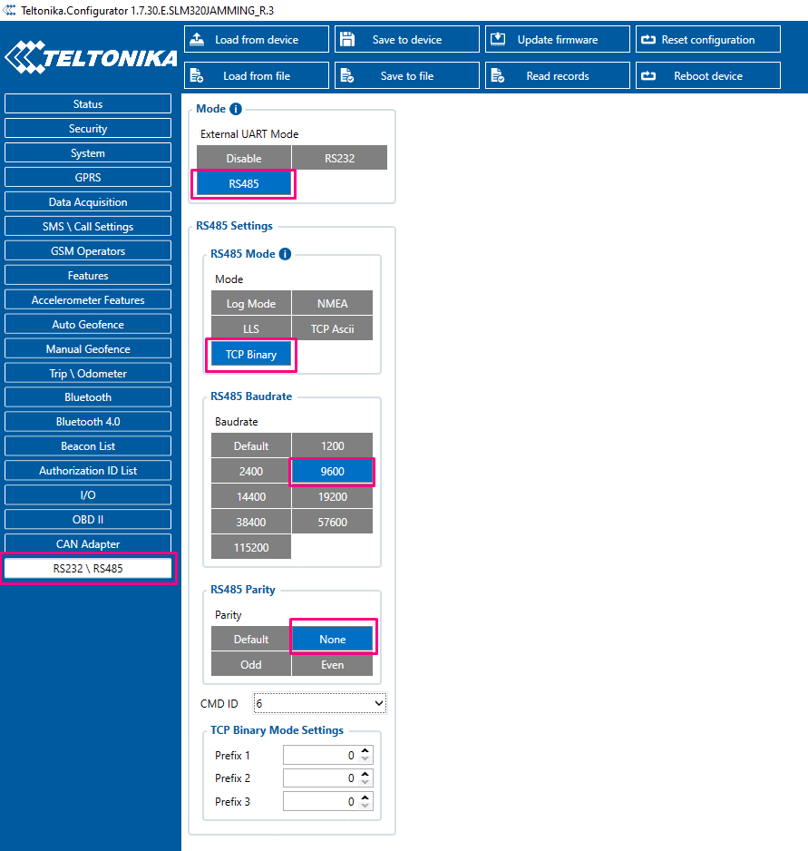
For the Modbus integration, we need to select RS485 as UART mode and TCP Binary as RS485 mode. Set the baud rate and parity as per the sensor configuration. In our case, the sensor baud rate is 9600 and parity is None. Leave the CMD ID field and Prefix settings as it is.
FMX6 series device configuration
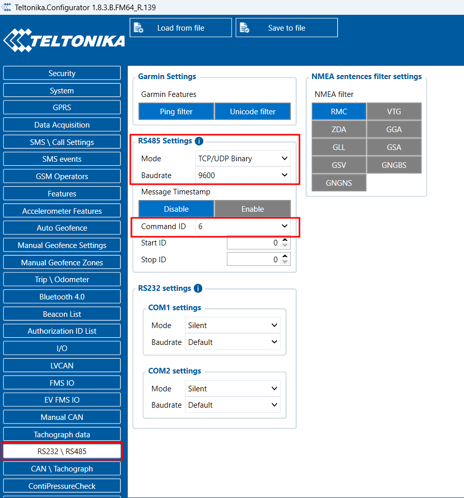
For the Modbus integration, we need to select RS485 as mode and TCP/UDP Binary as RS485 mode. Set the baud rate as per the sensor's documentation.
Note: The parity on FMX650 is always set as "none." If the sensor’s default parity is not "none," it must be set to "none" to connect with the FMX650. If the parity cannot be changed on the sensor side and a specific parity type is required for sensor <-> FMC650 communication, please contact Teltonika support via the Partner Portal/HelpDesk or your sales manager.
In our case, the sensor baud rate is 9600 and parity is None.
Leave the CMD ID field and start ID, Stop ID settings as it is.
Creating the Modbus command
This sensor is using eight holding registers to store the data. We need to use Read Holding Registers (FC=03) Modbus function to read the values from these registers. Please find the sensor register address details below.
| Register Address | Meaning | Description | Read and Write |
|---|---|---|---|
| 0 | Temperature | The unit is 0.1 degree | Read only |
| 1 | Relative Humidity | The unit is 0.1% | Read only |
| 2 | Reserved 1 | Read only | |
| 3 | Reserved 2 | Read only | |
| 4 | Address code | Set by DIP switch | Read only |
| 5 | Baudrate | Support 4800, 9600, 19200 | Read and Write |
| 6 | Hardware version | Read only | |
| 7 | Software version | Read only |
We need to send the below Modbus command to the sensor to read the data from register addresses 0 to 7 (40001 to 40009).
01 03 0000 0008 440C
01:The Slave Address (Sensor address)
03:The Function Code
0000:The Data Address of the first register requested
0008:The total number of registers requested (Read 8 registers 40001 to 40009)
440C:The CRC (cyclic redundancy check) for error checking
Constructing the Codec 12 Command
As discussed in the beginning, we need to pack this Modbus command as Codec 12 command then only we can send it from the server. Please find the below structure of a Codec 12 command.
Command message structure:
| 0x00000000 (Preamble) | Data Size | Codec ID | Command Quantity 1 | Type (0x05) | Command Size | Command | Command Quantity 2 | CRC-16 |
|---|---|---|---|---|---|---|---|---|
| 4 bytes | 4 bytes | 1 byte | 1 byte | 1 byte | 4 bytes | X bytes | 1 byte | 4 bytes |
Preamble - the packet starts with four zero bytes.
Data Size - size is calculated from the Codec ID field to the second command or response quantity field.
Codec ID - in Codec12 it is always 0x0C.
Command/Response Quantity 1 - it is ignored when parsing the message.
Type - 0x0E – If you set the type as 0E the device will route this command to serial ports ( Only for FMX125/FMX225)
Command/Response Size – command or response length.
Command/Response – command or response in HEX.
Command/Response Quantity 2 - a byte that defines how many records (commands or responses) is in the packet. This byte will not be parsed but it’s recommended that it should contain the same value as Command/Response Quantity 1.
CRC-16 – calculated from Codec ID to the Command Quantity 2. CRC (Cyclic Redundancy Check) is an error-detecting code used to detect accidental changes to RAW data.
Let‘s create our GPRS command as per the codec 12 protocol for FMX125/225
010300000008440C is the Modbus command; we have used this command as the payload of our GPRS command.
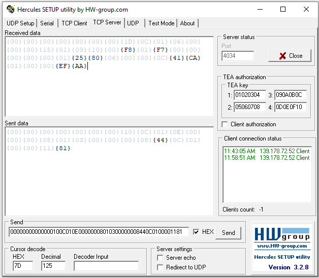
00000000 00000010 0C 01 0E 00000008 010300000008440C 01 00001181
Now, let‘s create our GPRS command as per the codec 12 protocol for FMX6 series devices.
010300000008440C is the Modbus command; we have used this command as the payload of our GPRS command.
00000000 00000010 0C 01 05 00000008 010300000008440C 01 0000DA8B
05 -> The command ID is dependent on the value we select in the configurator. For command Type, you have to use configured Command ID -1. By default, we are using command ID 6 in the configuration. Therefore, the command from sever has to be with 05 and the response from the sensor to the server will have command ID 06 in the codec packet.
Sensor response
Please find the below sensor response for the Modbus command to read eight holding registers. The device will pack this response in a Codec 12 packet and send it to the server. So, in the server, we will get the codec 12 response from the device, and we need to parse this as per the codec 12 protocol to get the sensor response. This is the response from the device for the Modbus command.
00000000 0000001D 0C 01 06 00000015 010310010901B500000000000125800600000C489C 01 0000EFAA
If we parse this message as per the codec 12 protocol, we will get the original Modbus response from the sensor i.e., 01 03 10 0109 01B5 00000000 0001 2580 0600 000C 489C . We need to decode this data as per the Modbus protocol.
01:The Slave Address (Sensor address)
03:The Function Code
10:The number of bytes
0109:Temperature
01B5:Humidity
00000000:Reserved Bytes
0001:Sensor address
2580:Baud rate
0600:Hardware version
000C:Software version
489C :CRC
Data analysis
We need to analyze this data in the server as per the sensor user manual to get the correct values.
Temperature = 0109H
we need to do the hex-to-decimal conversion.
Hex2Dec (0109) = 265
Then we need to divide by 10 to get the temperature value in degree Celsius, 265/10 = 26.5 ℃
The same calculation we need to perform for the Humidity also.
Humidity = 01B5H
Hex2Dec (01B5) = 437 / 10 = 43.7%RH.
Baud rate = 2580, we need to do the hex-to-decimal conversion to get the baud rate.
Hex2Dec (2580) = 9600
Sample Codec 12 message frames
We have used Hercules as our test server. We have sent the command as HEX and received the response from the device.
Conclusion
Teltonika FMX125 & FMX650 devices are capable to integrate equipment and sensors that use Modbus RTU protocol. We have successfully integrated TZONE TZ-THT02 RS485 Modbus RTU Temperature and Humidity sensor with FMC125.


