Template:FMM640 Impulse Counters Settings
Impulse Counters Settings

Pulse counter functionality enables the FMX640 devices to count digital impulses going to Digital and Analog Inputs. This means that these inputs of the FMX640 devices can now be used for precise fuel flow meter data reading. Impulse based fuel usage monitoring is much more accurate than a different type of fuel metering sensors and it makes the FMX640 devices a perfect solution for high fuel usage machines like cranes, construction vehicles, mining machines, agriculture equipment.
How does it work?
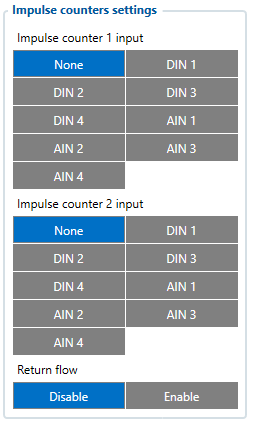
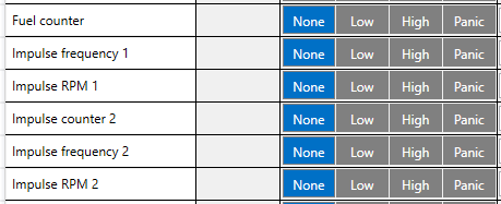
When "Impulse Counter 1/2 input" is selected and "Fuel Counter/Impulse Counter 2" IO elements are enabled, device will count every input state change to HIGH and send the counted number with the next record. Pulse counter value is reset after sending the record.
NOTE: Impulse Counters feature is available from FW ver. 01.02.02
I/O elements - Each counter has a corresponding IO elements for "Impulse Frequency" - value in Hz and "Impulse RPM" - impulse count per minute.

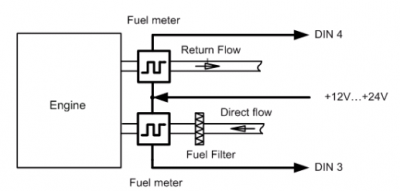
Additionally - some fuel meters have a return flow counter as well:

In this case - you can select which inputs are used for direct (Impulse counter 1) and return (Impulse counter 2) lines and enable "Return Flow" - when this parameter is enabled - "Fuel Counter" IO element will have a value of Direct Flow impulses substracted by Return Flow impulses.
For example:
- Direct Flow=50 impulses.
- Return Flow=10 impulses
- Fuel Counter=40 - if "Return Flow" is enabled.
Note that each Input has a specific requirements for signal frequency and threshold:
| Input | Max frequency (Hz) | Min Voltage threshold (V) |
|---|---|---|
| DIN1 | 50 | 7.5 |
| DIN2 | 30 000 | 2.5 |
| DIN3 | 30 000 | 2.5 |
| DIN4 | 30 000 | 2.5 |
| AIN1 | 10 000 | 2.5 |
| AIN2 | 10 000 | 2.5 |
| AIN3 | 10 000 | 2.5 |
| AIN4 | 10 000 | 2.5 |
