Difference between revisions of "ADAS Camera Manual"
MindaugasK (talk | contribs) |
MindaugasK (talk | contribs) |
||
| Line 61: | Line 61: | ||
'''''Vehicle Data File''''' (CAN-BUS)For CAN-BUS connection, choose the ‘Vehicle info file’ tab and select ‘Choose File’ to upload the previously downloaded ‘mdasinfo.dat’ file (see ‘CAN-Equipped vehicles’ section). | '''''Vehicle Data File''''' (CAN-BUS)For CAN-BUS connection, choose the ‘Vehicle info file’ tab and select ‘Choose File’ to upload the previously downloaded ‘mdasinfo.dat’ file (see ‘CAN-Equipped vehicles’ section). | ||
[[File:Vehinst14.jpg|center|frameless|363x363px]] | [[File:Vehinst14.jpg|center|frameless|363x363px]] | ||
| + | |||
| + | ==Camera location and Vehicle Measurement== | ||
| + | Camera location and vehicle measurement can affect ADAS performance. It`s very important put accurate data for the best performance. | ||
| + | [[File:Vehinst15.png|center|frameless|404x404px|alt=]] | ||
| + | <table class="nd-othertables" style="width: 68%;"> | ||
| + | <th style="width: 10%; text-align:left; vertical-align:middle; color:black">Camera Option</th> | ||
| + | <th style="width: 20%; text-align:center; vertical-align:middle; color:black">Description</th> | ||
| + | </tr> | ||
| + | <tr> | ||
| + | <td style="width: 8%; text-align:left;">Camera Height</td> | ||
| + | <td style="width: 8%; text-align:left">Distance from ground to the center of camera lens.</td> | ||
| + | </tr> | ||
| + | <tr> | ||
| + | <td style="width: 8%; text-align:left">Camera Center</td> | ||
| + | <td style="width: 8%; text-align:left">Distance from the center of windshield to camera lens | ||
| + | “-“: Left Side / “+”:Right Side | ||
| + | |||
| + | (If ADAS is attached 5cm to the right from the center, input 5. | ||
| + | |||
| + | If ADAS is attached 5cm to the left from the center, input -5.) | ||
| + | </td> | ||
| + | </tr> | ||
| + | <tr> | ||
| + | <td style="width: 8%; text-align:left">Camera to Wheel</td> | ||
| + | <td style="width: 8%; text-align:left">Distance from the camera to the center of the wheel. | ||
| + | '''For trucks or buses''', some vehicles’ wheels are located behind. | ||
| + | |||
| + | In this case, please input 20cm. | ||
| + | </td> | ||
| + | </tr><tr><td>Vehicle Width</td><td>Distance between the wheels. | ||
| + | Measure distance from left outside boarder to right outside boarder of the wheels. | ||
| + | </td></tr><tr><td>Camera to bumper</td><td>Distance from the camera lens to the end of the bumper. | ||
| + | For trucks or buses, it is recommended to input 300 if sensitive FCW warning is needed. | ||
| + | </td></tr></table> | ||
| + | |||
| + | Camera angle – adjust the camera angle to locate the horizontal between the red guide lines. | ||
| + | [[File:Vehinst16.png|center|frameless|316x316px]] | ||
| + | In case of indoor installation or somewhere you cannot see the horizon properly, use same data to "'''Camera Height'''”. Mark the same height on the wall apart about 3 ~ 5 meters from the vehicle. | ||
| + | [[File:Vehinst17.png|center|frameless|332x332px]] | ||
| + | |||
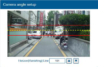
| + | Fine Camera Angle - For better accuracy of ADAS, locate the yellow dotted line in the horizon as close as possible. | ||
| + | [[File:Vehinst18.png|center|frameless|344x344px]] | ||
| + | |||
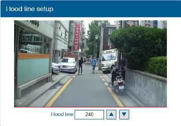
| + | Hood Line - Locate the red line at the end of the vehicle’s hood line to remove the useless area. | ||
| + | [[File:Vehinst19.png|center|frameless|360x360px]] | ||
| + | Please follow link for video instruction: https://www.youtube.com/watch?v=93wrc6j9aqA | ||
Revision as of 06:46, 30 August 2022
Main Page > Video Solutions > Teltonika ADAS > ADAS Camera ManualMain (front) camera unit preparation
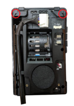
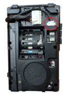
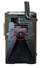
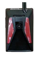
The main unit comes prepared for bus/large truck setup (cable routing) or vehicles with mostly vertical windshields. To set up the unit for an average truck or passenger vehicle, dismantle partially as shown below:
| Unit preparation | |||||
|---|---|---|---|---|---|
| 1. Remove cover | 2. Remove (2x) screws,
remove plastic cover |
3. Remove (2x) screws,
pry plastic mounting frame off Unit from corners | |||
| 4. Reroute the main
cable (and rear camera cable, if adding) around unit to front (glass side) |
5. Press tightly into
channels when routing cables. Remove front camera dust sticker |
6. Replace 1 cover only
removed from step 3. Replace 2 screws. Leave the remaining covers off until the last step | |||
ADAS Calibration
ADAS Calibration requires:
- a laptop with an internet connection and a browser
- micro-USB cable
- tape measure
- parking the car with a clear, open stretch of about a 45 meters unobstructed view (try to park close to your facility to keep the internet connection accessible – at least during the calibration driver installation)
- a partner to drive the vehicle while speed correction is performed
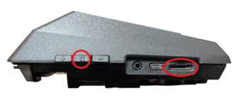
Before beginning, insert the provided micro-SD card into the main unit in the location shown below until it clicks and turn the Ignition ON. Wait for the prompt, then press and release the center button one time. After the successful prompt and the unit reboots, continue to step 1.
1. Park the vehicle in a spot with a clear stretch of unobstructed line-of-sight (about 45 meters). Leave the vehicle running
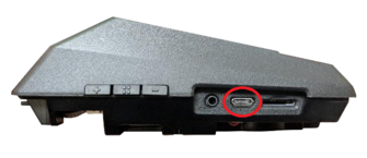
2. Connect the USB cable to the Mirco-USB port on the side of the main unit (windshield) and the other end to the laptop. If on a windows 10 machine, it should automatically install the required driver. If not or on an older machine, go to movon.co.kr, go to the ‘ADAS’ tab at the top then to ‘Downloads’ under Support. Download the appropriate zip file (contains driver) and extract it fully for your version of Windows OS (if using the 7/8 driver, install the .exe file). If WIN10, once downloaded, disconnect/reconnect the USB and it should automatically install, or find the unit in Device Manager and right-click, Update Driver and browse for driver locally.
3. Open Chrome browser again and type in ’10.0.0.1’ into the URL bar. If the driver was installed properly, the calibration screen will appear. Input credentials and press LOGIN USER: admin PASS: 1234
4. Select Vehicle Signal Type: there are several wiring options for installation: CAN-BUS / Analog (GPIO) / GPS (Speed). Select the proper calibration option based off which was installed: CAN (if CAN file is available), Analog (if analog signals were tapped)
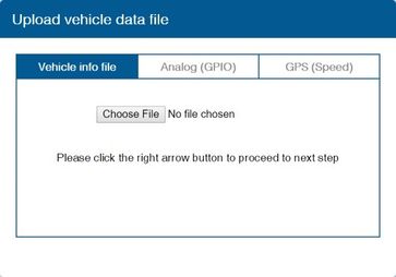
Vehicle Data File (CAN-BUS)For CAN-BUS connection, choose the ‘Vehicle info file’ tab and select ‘Choose File’ to upload the previously downloaded ‘mdasinfo.dat’ file (see ‘CAN-Equipped vehicles’ section).
Camera location and Vehicle Measurement
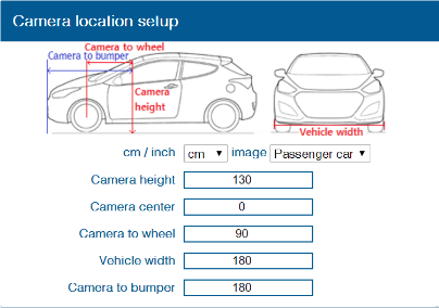
Camera location and vehicle measurement can affect ADAS performance. It`s very important put accurate data for the best performance.
| Camera Option | Description |
|---|---|
| Camera Height | Distance from ground to the center of camera lens. |
| Camera Center | Distance from the center of windshield to camera lens
“-“: Left Side / “+”:Right Side (If ADAS is attached 5cm to the right from the center, input 5. If ADAS is attached 5cm to the left from the center, input -5.) |
| Camera to Wheel | Distance from the camera to the center of the wheel.
For trucks or buses, some vehicles’ wheels are located behind. In this case, please input 20cm. |
| Vehicle Width | Distance between the wheels.
Measure distance from left outside boarder to right outside boarder of the wheels. |
| Camera to bumper | Distance from the camera lens to the end of the bumper.
For trucks or buses, it is recommended to input 300 if sensitive FCW warning is needed. |
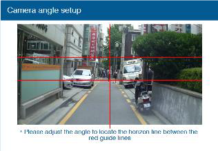
Camera angle – adjust the camera angle to locate the horizontal between the red guide lines.
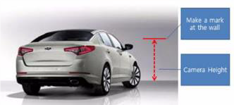
In case of indoor installation or somewhere you cannot see the horizon properly, use same data to "Camera Height”. Mark the same height on the wall apart about 3 ~ 5 meters from the vehicle.
Fine Camera Angle - For better accuracy of ADAS, locate the yellow dotted line in the horizon as close as possible.
Hood Line - Locate the red line at the end of the vehicle’s hood line to remove the useless area.
Please follow link for video instruction: https://www.youtube.com/watch?v=93wrc6j9aqA
