FTM305 Input/output (I/O)
Input / output (I/O)
Search
Enter the keyword to search for the desired permanent I/O.
More Filters
It provides additional filter options such as Priority, Operand, and rows with currently available values.
View Columns
Filters the necessary tabs when making configuration changes or viewing. Priority, Operand, Low Level, High Level, and Event Only Options are available filters. The Input name and Current Values are permanent columns.
Current Value
If the device is connected to the Telematics Configuration Tool, then all the current I/O values can be seen here.
Units
Units of measurement.
Priority
This field allows the enabling of the I/O elements and sets them a priority so they are added to the data packet, which is sent to the server.
By default I/O elements with Low priority are enabled: Total odometer GSM Signal, Battery Voltage, Battery Current, PCB temperature, GNSS PDOP, GNSS HDOP, Ignition, Movement, External voltage.
These records made by FTM305 device are regular, and regular packets are sent as low priority records.
Priority level (AVL packet priority) can be:
None Priority
- The module doesn't make additional records.
Low Priority
- The module makes an additional record with an indication that the event was caused by an I/O element change (depending on Operands configuration).
High Priority
- The module makes an additional record with High priority flag and sends event packet immediately to the server using GPRS.
High and Low Level
These levels define I/O value range. If I/O value enters or exits this range, FTM305 generates an event.
Event Only
When this is selected, I/O element status value will be appended only to eventual records, otherwise I/O element status value will appear in each AVL record.
Operands
Defines when to generate event: On Exit, On Entrance, On Both, Monitoring, On Hysteresis, On Change or On Delta Change.
Operand Monitoring
No event at all. Values are recorded only when other triggers worked.
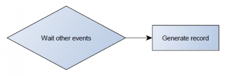
Operand On Change
Record is generated when input value changes.

Operand On Exit
Record is generated when input value leaves a range between low and high level limits.

Operand On Entrance
Record is generated when input value enters a range between low and high level limits.
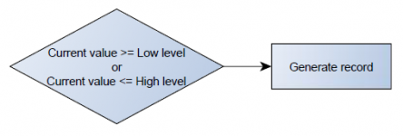
Operand On Both
Record is generated by both On Exit and On Entrance operands' logic at same time.

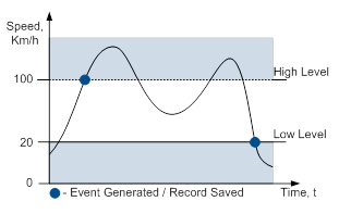
Operand On Hysteresis
Record is generated when input value crosses the high limit value from below the low limit value or vice versa.
Operand On Delta Change
Record is generated when input value changes and the absolute change becomes equal to or higher than the limit value.

Permanent I/O
When no permanent I/O elements are enabled, AVL packet comes with GNSS information only.
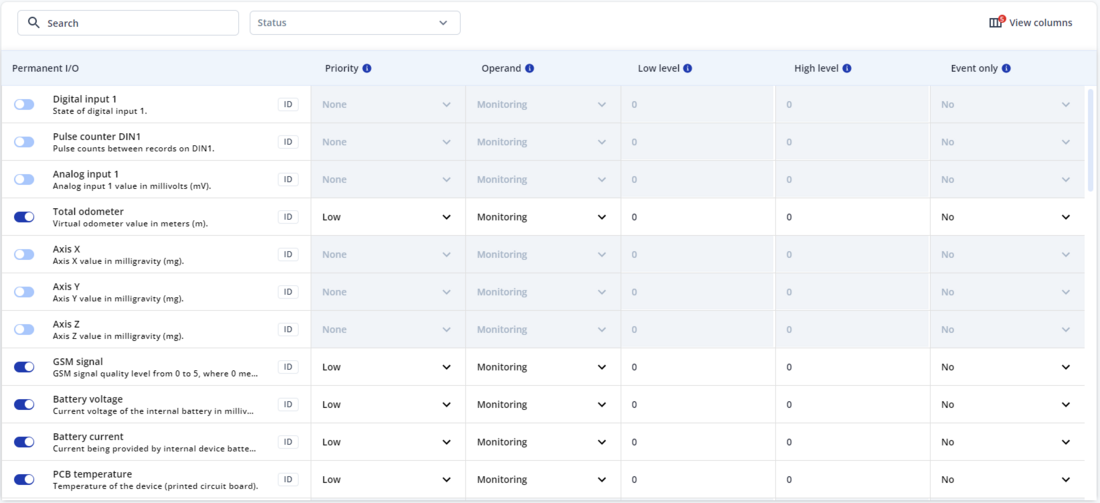
After enabling I/O element(s) AVL packet contains current value(s) of enabled I/O element(s) along with GNSS information.
Manual CAN
Manual CAN functionality allows user to read data from CAN BUS without requiring an additional CAN protocol development from the firmware side.
Note: Before using Manual CAN, make sure to select the correct CAN settings: FTM305 CAN settings.
Up to 70 Manual CAN I/Os can be configured:
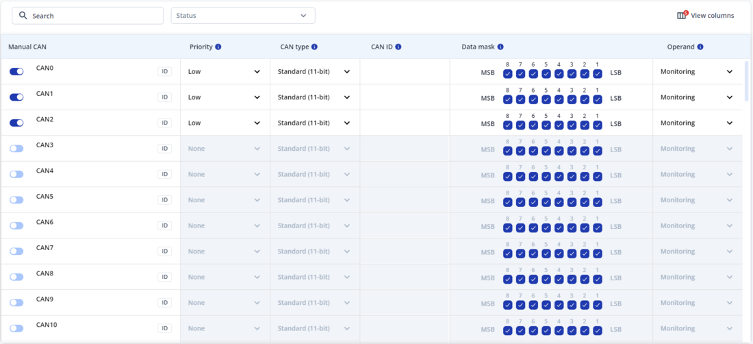
Configurable settings:
- Priority - defines the priority of Manual CAN I/O:
- Low - enables the I/O element, adding its value to periodic or eventual record packets based on the "Operand" and "Event only" settings. Events are sent along with periodic data according to the "Data acquisition" configuration.
- High - enables the I/O element with high priority, immediately sending its value to the server in a high-priority eventual record. If the "Operand" is set to "Monitoring," it functions the same as "Low Priority."
- CAN type - defines which CAN ID type will be received and requested:
- Standard - uses 11 bits to read the CAN ID, allowing for 2,048 unique IDs (0x000 to 0x7FF).
- Extended - uses 29 bits to read the CAN ID, allowing for 536,870,912 unique IDs (0x00000000 to 0x1FFFFFFF).
- CAN ID – depends on CAN Type parameter and defines which CAN ID will be received by device.
- This identifier is composed of 4 bytes.
- For SAE J1939, the first and last bytes can vary depending on the vehicle make or model, while the bytes in between remain the same for all vehicles. Although the first and last bytes may hold any value, it is recommended to use FF for both.
- Data mask – defines which data bytes are sent to the server (sometimes not all data bytes are necessary). Up to 8 particular data bytes can be selected for each CAN ID.
- Operand – defines when to generate event:
- Monitoring - continuously monitors the current I/O element value in with every periodical record. No eventual records are created when using the "Monitoring" operand.
- On Change - generates an eventual record whenever the input value changes.
Manual CAN Commands
Manual CAN Commands functionality allows user to send configurable commands to CAN BUS.
Note: Before using Manual CAN, make sure to select the correct CAN settings: FTM305 CAN settings.
Up to 10 Manual CAN Command I/Os can be configured:

Configurable settings:
- Command type - defines which CAN ID type will be used to send commands:
- Standard (11-bit) - a maximum value of 7FF.
- Extended (29-bit) - a maximum value of 1FFFFFFF.
- CAN ID – defines command CAN ID.
- If Command type is Standard (11-bit) - a maximum value of 7FF.
- If Command type is Extended (29-bit) - a maximum value of 1FFFFFFF.
- Data - defines command data.
- Data length - defines command data length in bytes.
- Send type - selects command send type:
- Once - command will be sent one time after it is triggered.
- Periodic - command will be sent periodically after it is triggered.
- Response - command will be sent once as a response to received Manual CAN I/O.
- Run on startup - if enabled, command will be triggered automatically on device startup.
- Response - if Send type is Response, defines Manual CAN I/O which will trigger command.
- Send period - defines command send period (in miliseconds) if Periodic send type is selected:
- Minimal command period - 100 ms.
- Period must be configured with a step of 100 ms.
- Send count - defines command sending count if Periodic send type is selected.
- If set to 0 - command will be sent infinitely until it is turned off by the user.
After configuring, Manual CAN commands can be triggered with SMS/GPRS commands: FTM305 SMS/GPRS Commands.
