Speed Limiting Solution FMC130+ETC
Introduction
The loss incurred globally by corporate fleet and insurance businesses due to accidents caused by over speeding is significant. This can often lead to the loss in productivity and multiple other evident collateral damage costs. We at Teltonika Telematics have developed a unique solution to help tackle over speeding in the fleet.
Solution description
Using the combination of Teltonika FM device with the Automotive relay and the Electronic throttle controller to achieve speed limiter feature.
What you need for a solution?
- FMC130 device
- Electronic Throttle Controller
- Automotive Relay
- The SIM card in order to get data to your server
- FOTA WEB to remotely send the configuration to the device.
- *Solenoid Valve
*Solenoid Valve is optional for one of the wiring schemes shown below
Installation
This solution can be implemented in 3 different ways based on the speed limiting scenario. It’s important to install the device and the relay in an hidden place inside dashboard.
Although devices have high gain antennas it’s important to mount devices with stickers on top and in metal-free space. The device should be firmly fixed to the surface or cables. Please make sure, that device is not fixed to heat emitting or moving parts.
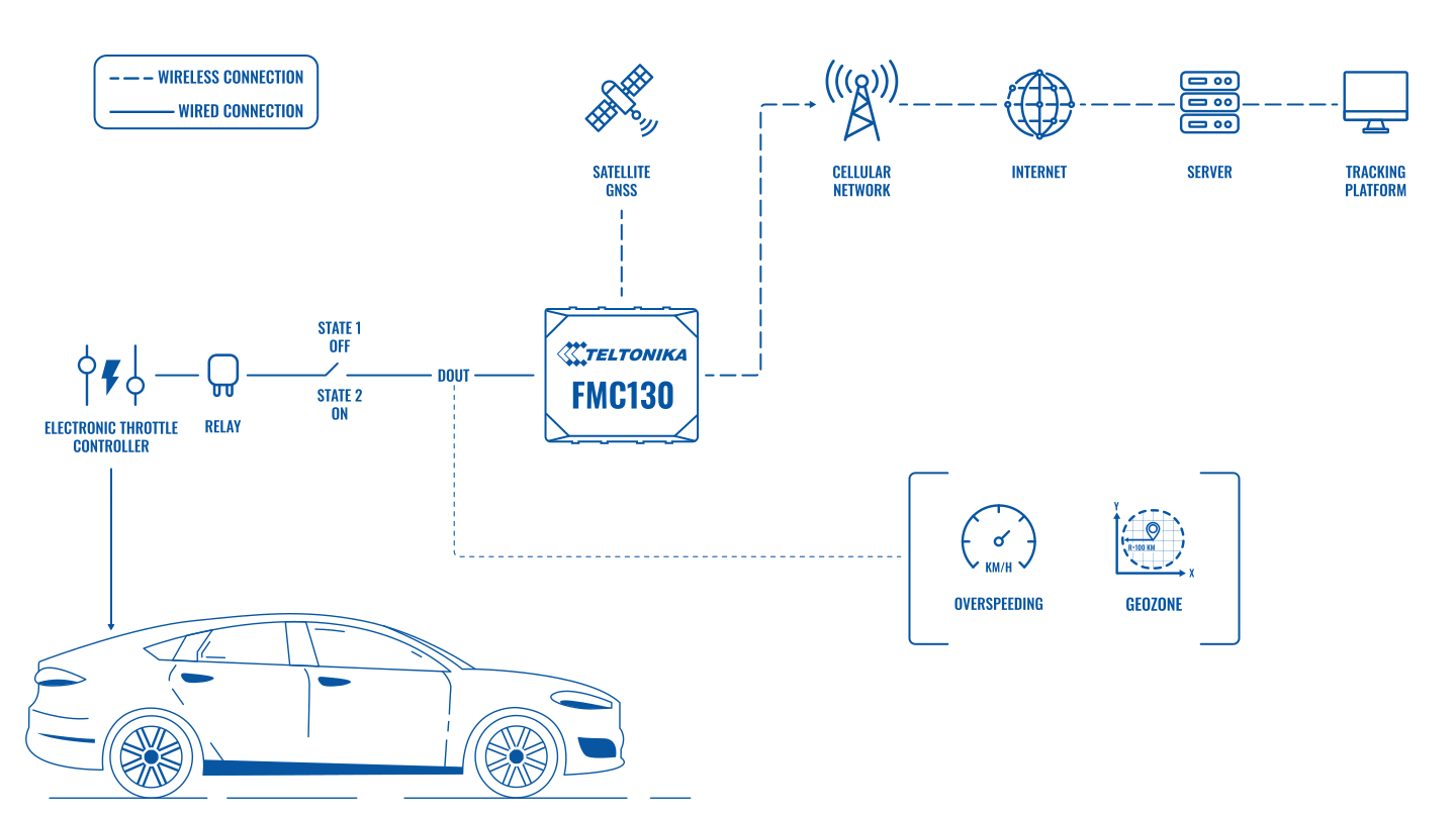
To have a working solution it’s important to properly wire the devices. In the picture below it's shown how to correctly wire the device when implementing electronic throttle controller solution.
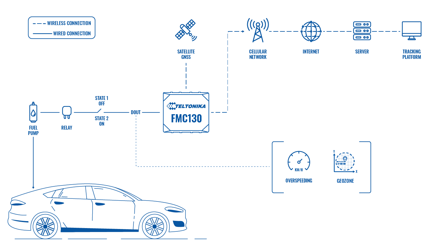
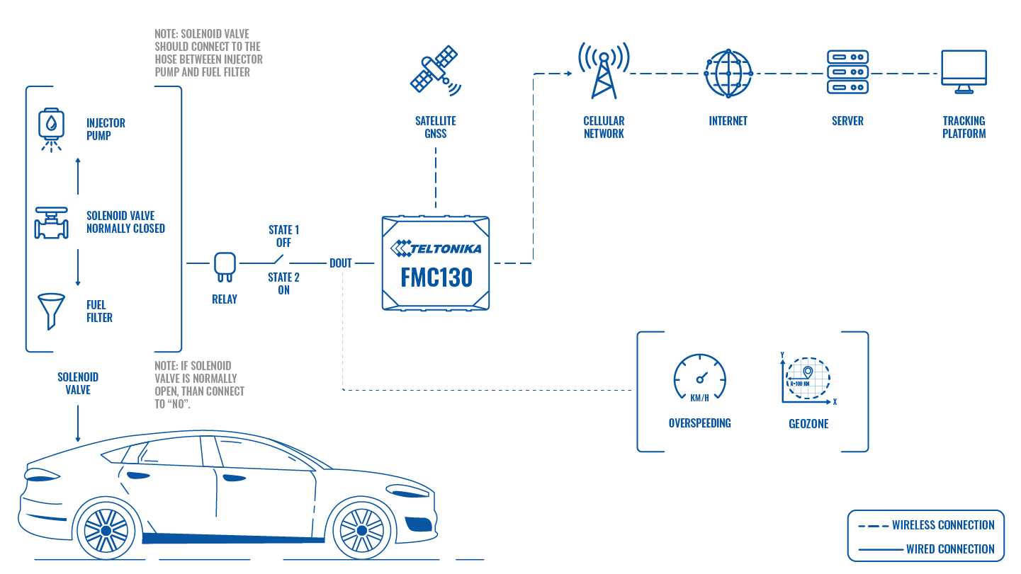
There are 3 ways of connecting the FM device which are displayed below:
A. Installation - Electronic Throttle Controller
B. Installation - Fuel Pump
C. Installation - Solenoid Valve
Wiring Scheme
Relay Wiring Scheme
| Relay PIN | Relay cable color | Connection |
|---|---|---|
| 30 | Blue | +VDC (Common connection to NO & NC terminals) |
| 85 | Black | DOUT of FM Device |
| 86 | White | +VDC (Coil) |
| 87 | Yellow | Not Required to connect (Normally Open (NO)) |
| 87a | Red | Green Wire from ETC or Wire to Fuel Pump or Wire to Solenoid Valve |
ETC Wiring Scheme
| ETC cable color | Connection |
|---|---|
| Red | +VDC (+10...32) |
| Black | Ground |
| Green | PIN 87a (NC of Relay) |
| White | V-/0.40V from Accelerator pedal |
| Brown | V+/0.70V from Accelerator Pedal |
| Yellow | S+/0.70V from ECU |
| Grey | S-/0.40V from ECU |
Note: Voltage may vary depending on vehicle model.
During installation please follow recommendations in order to avoid damaging device and vehicle:
- while the connecting the wires, please ensure the module is not plugged IN.
- Ensure the car ECU falls asleep, measure voltage on the chosen wire if it is still available. It usually takes 5 to 30 minutes period for the ECU to completely shutdown depending on the model of the vehicle.
- When the module is connected, be sure to measure the voltage again if it did not decrease.
- The ground wire is connected to the vehicle frame or metal parts that are fixed to the frame.
Configuration
1. Prerequisites:
1.1. Read through First start guide
1.2. Understanding of possible Sleep modes.
2. Configuration - Speed limiting:
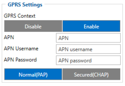
Parameter ID – Parameter name GPRS settings:
- 2001 – APN
- 2002 – APN username (if there are no APN username, empty field should be left)
- 2003 – APN password (if there are no APN password, empty field should be left)
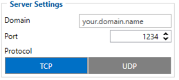
Server settings:
- 2004 – Domain
- 2005 – Port
- 2006 – Data sending protocol (0 – TCP, 1 – UDP)
After successful GPRS/SERVER settings configuration, FM device will synchronize time and update records to the configured server. Time intervals and default I/O elements can be changed by using Teltonika Configurator or SMS parameters.
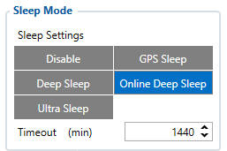
Sleep settings:
- 102 – Sleep settings(0 – Disable, 1 – Gps sleep, 2 – Deep sleep, 3 – Online Deep sleep, 4 – Ultra sleep)
Note: This scenario will not work with Deep Sleep and Ultra Sleep modes, since they disable the device's GSM module to save power.
To setup the speed limiting feature in the configurator we should navigate to Features → Over Speeding where we would set a priority for the event, speed source and DOUT 1 for the relay to work properly.
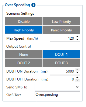
Over speeding settings
- 11100 – Scenario settings(0 – Disable, 1 – Low Priority, 2 – High Priority, 3 – Panic Priority)
- 11104 - Max Speed (Default value - 90 km/h)
- 11103 - Output Control (0 - None (Default), 1 - DOUT1), DOUT1 needs to be enabled to use the speed limiting feature
Note: Detected speed has to be greater than (configured max speed +3% of configured max speed) for Over speed start event; detected speed has to be lower than(configured max speed -3% of configured max speed) for Over speed end event.
Quickstart: From default configuration to Speed Limiting solution in one SMS:
" setparam 2001:APN;2002:APN_user;2003:APN_password;2004:Domain;2005:Port;2006:0;102:3;11100:2;11104:90;13217:0;13223:8;11103:1;11101:5000;11102:0"
This SMS will set up your device to report the Speed Limiting scenario to the server.
Note: Before SMS text, two space symbols should be inserted if no SMS username or password was set in SMS \ Call settings.
3. Configuration - Speed Limiting based on Geo-Fence
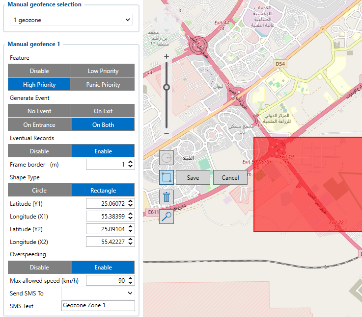
Manual Geofence settings
- 20100 – Scenario settings(0 – Disable, 1 – Low Priority, 2 – High Priority, 3 – Panic Priority)
- 20101 - Generate Event(0 - Disable, 1 - Low Priority, 2 - High Priority, 3 - Panic Priority)
- 20104 - Shape Type(0 - Circle,1 - Rectangle)
- 20105 - Radius in Metres
- 20106 - X1 Coordinate
- 20107 - Y1 Coordinate
- 20108 - X2 Coordinate
- 20109 - Y2 Coordinate
- 20110 - Overspeeding(0 - Disable, 1- Enable) should be enabled for speed limiting functionality.
- 2005 - Max allowed speed km/h.
Note: Detected speed has to be greater than (configured max speed +3% of configured max speed) for Over speed start event; detected speed has to be lower than(configured max speed -3% of configured max speed) for Over speed end event.
Parsing information
1.Prerequisites:
1.1. Open TCP/UDP port
1.2. Read Java parser first start guide
2. Parsing example:
| Unparsed received data in hexadecimal stream |
|---|
|
00000000000000758E010000018494E2DAFA000F0E53AE209AB86A007F00110D000000FF0015000800EF0100F00100500100150300C800009B0300010000B301000A00B5000A00B6000 600423FC9001800000043000000440000001100220012FFBA0013FC34000F0000000200F10000601A0010002D97E0000000000100002136 |
| AVL Data Packet Part | HEX Code Part |
|---|---|
| Zero Bytes | 00 00 00 00 |
| Data Field Length | 00 00 00 75 |
| Codec ID | 8E (Codec 8 Extended) |
| Number of Data 1 (Number of Total Records) | 01 |
| Timestamp | 00 00 01 7C B7 A5 73 70 00 (Monday, October 25, 2021 4:30:46 PM GMT+03:00) |
| Priority | 00 |
| Longitude | 0F 0E 53 AE |
| Latitude | 20 9A B8 6A |
| Altitude | 00 7F |
| Angle | 00 11 |
| Satellites | 0D |
| Speed | 00 00 |
| Event IO ID | 00 FF (Over Speeding) |
| N of Total ID | 00 15 |
| N1 of One Byte IO | 00 08 |
| 1’st IO ID | EF (AVL ID: 239, Name: Ignition) |
| 1’st IO Value | 01 |
| 2’nd IO ID | F0 (AVL ID: 240, Name: Movement) |
| 2’nd IO Value | 01 |
| 3’rd IO ID | 50 (AVL ID: 80, Name: Data Mode) |
| 3’rd IO Value | 01 |
| 4'th IO ID | 15 (AVL ID: 21, Name: GSM Signal) |
| 4'th IO Value | 01 |
| 5'th IO ID | C8 (AVL ID: 200, Name: Sleep Mode) |
| 5'th IO Value | 00 |
| 6'th IO ID | 009B (AVL ID: 155, Name: Geofence zone 01) |
| 6'th IO Value | 00 |
| 7'th IO ID | 01 (AVL ID: 1, Name: Digital Input 1) |
| 7'th IO Value | 01 |
| 8'th IO ID | B3 (AVL ID: 179, Name: Digital Output 1 ) |
| 8'th IO Value | 01 |
| N2 of Two Byte IO | 0A |
| 1’st IO ID | B5 (AVL ID: 181, Name: GNSS PDOP) |
| 1’st IO Value | 00 0A |
| 2’nd IO ID | B6 (AVL ID: 182, Name: GNSS HDOP) |
| 2’nd IO Value | 00 06 |
| 3’rd IO ID | 42 (AVL ID: 66, Name: External Voltage) |
| 3’rd IO Value | 3F C9 |
| 4'th IO ID | 18 (AVL ID: 24, Speed) |
| 4'th IO Value | 5F |
| 5'th IO ID | 43 (AVL ID: 67, Battery Voltage) |
| 5'th IO Value | 00 07 |
| 6'th IO ID | 44 (AVL ID: 68, Battery Current) |
| 6'th IO Value | 00 C8 |
| 7'th IO ID | 11 (AVL ID:17, Axis X) |
| 7’th IO Value | 00 22 |
| 8'th IO ID | 12 (AVL ID:18, Axis Y) |
| 8’th IO Value | FF BA |
| 9'th IO ID | 13 (AVL ID:19, Axis Z) |
| 9'th IO Value | FC 34 |
| 10'th IO ID | 0F (AVL ID: 15, ECO Score) |
| 10'th IO Value | 00 00 |
| N4 of Four Byte IO | 00 02 |
| 1'st IO ID | F1 (AVL ID: 241, Name: Active GSM Operator) |
| 1’st IO Value | 00 00 00 10 |
| 2’nd IO ID | 10 (AVL ID: 16, Name: Total Odometer) |
| 2’nd IO Value | 00 2D 97 E0 |
| N8 of Eight Byte IO | 00 00 |
| NX of X Byte IO | 00 00 |
| Number of Data 2 (Number of Total Records) | 01 |
| CRC-16 | 00 00 7F CF |
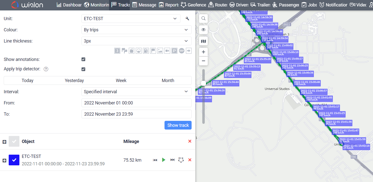
Demonstration in Wialon platform
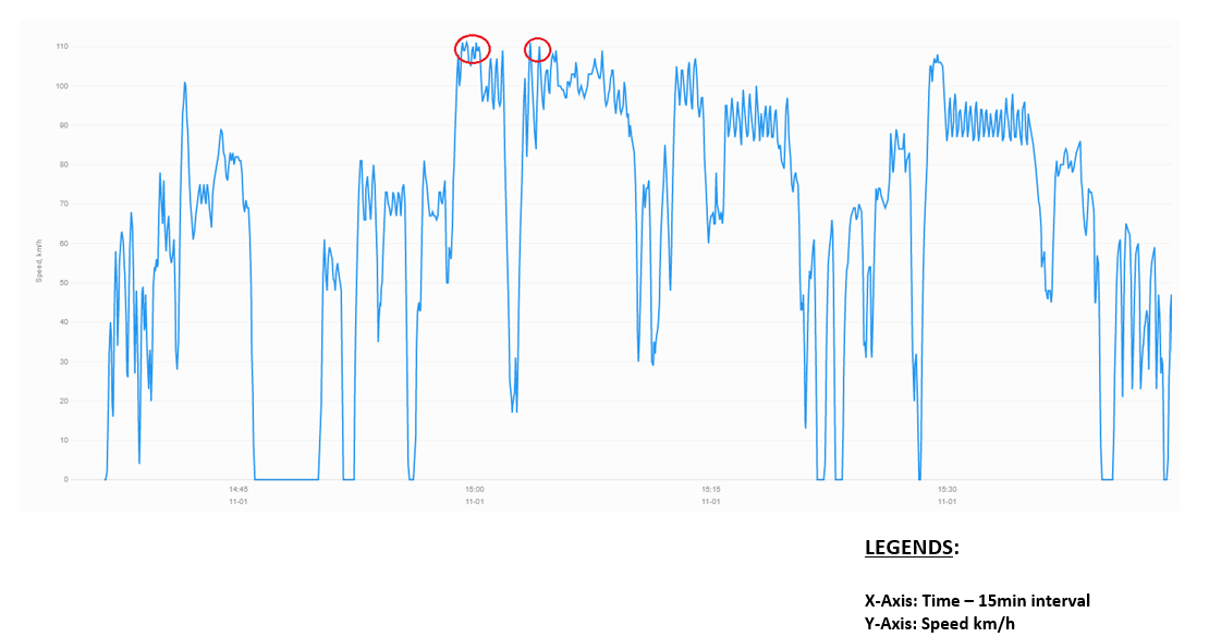
Wialon: Open Wialon application → Select unit→ Select Device → Select the date interval → Select Track→ to access all the information.
Graphical Representation:
Conclusion
Speed limiting is achieved when max speed is exceeded. Relay is activated on DOUT1 which will disable the acceleration pedal, turn off the fuel pump or close the solenoid valve.
Note: Detected speed has to be greater than (configured max speed +3% of configured max speed) for Over speed start event; detected speed has to be lower than(configured max speed -3% of configured max speed) for Over speed end event.

