Difference between revisions of "FM3001 First Start"

From Wiki Knowledge Base | Teltonika GPS
(19 intermediate revisions by 9 users not shown)
Line 1: Line 1:
{{Template:FM3_First_start_card|model=FM3001|pic=[[Image:FM3001_00_demo.png|400px|right]]}}
+
{{Template:FM3_First_start_card|model=FM3001}}
  
=='''OBD II pinout'''==
+
 
 +
 
 +
<font size="+3"><span style=color:#104996>'''OBD II pinout'''</span></font>
 +


{| class="wikitable"
 
{| class="wikitable"
 
|+
 
|+
! style="width:10%; border: 1px solid white; border-bottom: 2px solid #0054A6; background: white; color: #0054A6; text-align: left;"| PIN NUMBER
+
! style="background: white; color: #F6A83E;"         | Pin number 
! style="width:15%; border: 1px solid white; border-bottom: 2px solid #0054A6; background: white; color: #0054A6; text-align: left;"| PIN NAME
+
| style="background: white; color: #F6A83E;"         | Pin name
! style="width:30%; border: 1px solid white; border-bottom: 2px solid #0054A6; background: white; color: #0054A6; text-align: left;"| DESCRIPTION
+
| style="background: white; color: #F6A83E;"         | Description
| style="border: 1px solid white; border-bottom: 2px solid #E8E8E8; text-align: left; vertical-align: center; background: white;" rowspan="11" | [[Image:OBD_data_10-30V_pinout.jpg|400px|center]]
+
| style="background: white; color: #F6A83E;" rowspan="11" | [[Image:Fmb010_obdii_pinout.png|400px|center]]
 
|-
 
|-
| style="border: 1px solid white; border-bottom: 2px solid #E8E8E8; text-align: left; vertical-align: center; background: white;"|
+
| style="text-align: left; background: #F6F6FB;"         | 1
| style="border: 1px solid white; border-bottom: 2px solid #E8E8E8; text-align: left; vertical-align: center; background: white;"|
+
| style="text-align: left; background: #F6F6FB;"         | '''DIN1'''
| style="border: 1px solid white; border-bottom: 2px solid #E8E8E8; text-align: left; vertical-align: center; background: white;"|  
+
| style="text-align: left; background: #F6F6FB;"         | Ignition input.
 
|-
 
|-
| style="border: 1px solid white; border-bottom: 2px solid #E8E8E8; text-align: left; vertical-align: center; background: white;"| 2
+
| style="text-align: left; background: #F6F6FB;"         | 2
| style="border: 1px solid white; border-bottom: 2px solid #E8E8E8; text-align: left; vertical-align: center; background: white;"| '''PWM_BUS+/VPW'''
+
| style="text-align: left; background: #F6F6FB;"         | '''PWM_BUS+/VPW'''
| style="border: 1px solid white; border-bottom: 2px solid #E8E8E8; text-align: left; vertical-align: center; background: white;"|
+
| style="text-align: left; background: #F6F6FB;"         |
 
|-
 
|-
| style="border: 1px solid white; border-bottom: 2px solid #E8E8E8; text-align: left; vertical-align: center; background: white;"| 4
+
| style="text-align: left; background: #F6F6FB;"         | 4
| style="border: 1px solid white; border-bottom: 2px solid #E8E8E8; text-align: left; vertical-align: center; background: white;"| '''GND''' (-)
+
| style="text-align: left; background: #F6F6FB;"         | '''GND''' (-)
| style="border: 1px solid white; border-bottom: 2px solid #E8E8E8; text-align: left; vertical-align: center; background: white;"| Ground.
+
| style="text-align: left; background: #F6F6FB;"         | Ground.
 
|-
 
|-
| style="border: 1px solid white; border-bottom: 2px solid #E8E8E8; text-align: left; vertical-align: center; background: white;"| 5
+
| style="text-align: left; background: #F6F6FB;"         | 5
| style="border: 1px solid white; border-bottom: 2px solid #E8E8E8; text-align: left; vertical-align: center; background: white;"|'''GND''' (-)
+
| style="text-align: left; background: #F6F6FB;"         |'''GND''' (-)
| style="border: 1px solid white; border-bottom: 2px solid #E8E8E8; text-align: left; vertical-align: center; background: white;"| Ground.
+
| style="text-align: left; background: #F6F6FB;"         | Ground.
 
|-
 
|-
| style="border: 1px solid white; border-bottom: 2px solid #E8E8E8; text-align: left; vertical-align: center; background: white;"| 6
+
| style="text-align: left; background: #F6F6FB;"         | 6
| style="border: 1px solid white; border-bottom: 2px solid #E8E8E8; text-align: left; vertical-align: center; background: white;"| '''CAN_H'''
+
| style="text-align: left; background: #F6F6FB;"         | '''CAN_H'''
| style="border: 1px solid white; border-bottom: 2px solid #E8E8E8; text-align: left; vertical-align: center; background: white;"| CAN high.
+
| style="text-align: left; background: #F6F6FB;"         | CAN high.
 
|-
 
|-
| style="border: 1px solid white; border-bottom: 2px solid #E8E8E8; text-align: left; vertical-align: center; background: white;"| 7
+
| style="text-align: left; background: #F6F6FB;"         | 7
| style="border: 1px solid white; border-bottom: 2px solid #E8E8E8; text-align: left; vertical-align: center; background: white;"| '''K-Line'''
+
| style="text-align: left; background: #F6F6FB;"         | '''K-Line'''
| style="border: 1px solid white; border-bottom: 2px solid #E8E8E8; text-align: left; vertical-align: center; background: white;"|
+
| style="text-align: left; background: #F6F6FB;"         |
 
|-
 
|-
| style="border: 1px solid white; border-bottom: 2px solid #E8E8E8; text-align: left; vertical-align: center; background: white;"| 10
+
| style="text-align: left; background: #F6F6FB;"         | 10
| style="border: 1px solid white; border-bottom: 2px solid #E8E8E8; text-align: left; vertical-align: center; background: white;"| '''PWM_BUS-'''
+
| style="text-align: left; background: #F6F6FB;"         | '''PWM_BUS-'''
| style="border: 1px solid white; border-bottom: 2px solid #E8E8E8; text-align: left; vertical-align: center; background: white;"|  
+
| style="text-align: left; background: #F6F6FB;"         |  
 
|-
 
|-
| style="border: 1px solid white; border-bottom: 2px solid #E8E8E8; text-align: left; vertical-align: center; background: white;"| 14
+
| style="text-align: left; background: #F6F6FB;"         | 14
| style="border: 1px solid white; border-bottom: 2px solid #E8E8E8; text-align: left; vertical-align: center; background: white;"| '''CAN_L'''
+
| style="text-align: left; background: #F6F6FB;"         | '''CAN_L'''
| style="border: 1px solid white; border-bottom: 2px solid #E8E8E8; text-align: left; vertical-align: center; background: white;"| CAN low.
+
| style="text-align: left; background: #F6F6FB;"         | CAN low.
 
|-
 
|-
| style="border: 1px solid white; border-bottom: 2px solid #E8E8E8; text-align: left; vertical-align: center; background: white;"| 15
+
| style="text-align: left; background: #F6F6FB;"         | 15
| style="border: 1px solid white; border-bottom: 2px solid #E8E8E8; text-align: left; vertical-align: center; background: white;"| '''L-Line'''
+
| style="text-align: left; background: #F6F6FB;"         | '''L-Line'''
| style="border: 1px solid white; border-bottom: 2px solid #E8E8E8; text-align: left; vertical-align: center; background: white;"|
+
| style="text-align: left; background: #F6F6FB;"         |
 
|-
 
|-
| style="border: 1px solid white; border-bottom: 2px solid #E8E8E8; text-align: left; vertical-align: center; background: white;"| 16
+
| style="text-align: left; background: #F6F6FB;"         | 16
| style="border: 1px solid white; border-bottom: 2px solid #E8E8E8; text-align: left; vertical-align: center; background: white;"| '''VCC''' (10 - 30)V DC (+)
+
| style="text-align: left; background: #F6F6FB;"         | '''VCC''' (10 - 30)V DC (+)
| style="border: 1px solid white; border-bottom: 2px solid #E8E8E8; text-align: left; vertical-align: center; background: white;"| Power supply (+10..+30 V DC).
+
| style="text-align: left; background: #F6F6FB;"         | Power supply (+10..+30 V DC).
 
|-
 
|-
 
|}
 
|}


{{Template:FMB_First_start_config|model=FM3001|config_link=[[FM3001 Configuration|here]]|cfg_connect=Configurator_connect-FM3001.jpg|dc_voltage=10-30 V|family=FMB0}}
+
{{Template:FM3 First start config|model=FM3XXX|config_link=[[FM3XXX Configuration|here]]}}
  
{{Template:Mounting_recommendations
 
|mounting_recommendations=
 
|FMB2_installation_instruction=
 
|voltage={{{voltage|+10..+30}}}
 
|model=FMB3001
 
|connecting=
 
|FMB2_connecting_cables=
 
|unmounting=
 
|zone_of_limited=
 
|FMB_precautions=
 
|boats=
 
}}
 
  
https://teltonika-gps.com/product/fm3001/
+
{{Template:FMB0 Mounting recommendations|model=FMB001}}
  
[[Category:FM3001]]
+
https://teltonika.lt/product/fm3001/

Revision as of 08:44, 30 May 2018

Main Page > EOL Products > FM3001 > FM3001 First Start
Qsg rut950 teltonika.PNG

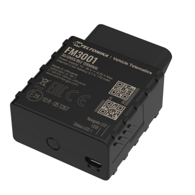
Advanced Plug and Track real-time tracking terminal with GNSS, 3G and Bluetooth connectivity

FM3001 00 demo.png


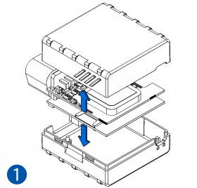
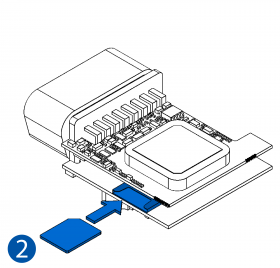
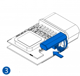
How to insert Micro-SIM card

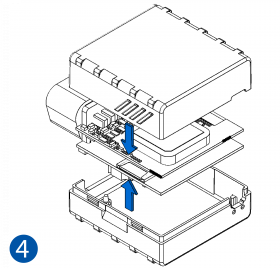
  1. Gently remove FM3001 cover using plastic pry tool from both sides.
  2. Insert Micro-SIM card as shown with PIN request disabled or read Security info how to enter it later in Configurator. Make sure that Micro-SIM card cut-off corner is pointing forward to slot.
  3. Connect battery as shown to device. Position the battery in place where it does not obstruct other components.
  4. Attach device cover back.
  5. Device is ready to be connected.

FM3001 1.png FM3001 2.png FM3001 3.png FM3001 4.png

Alert.png
Micro-SIM card insertion/removal must be performed when device is powered off – external voltage and internal battery disconnected. Otherwise Micro-SIM card might be damaged or device will not detect it.


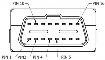
OBD II pinout


Pin number Pin name Description
Fmb010 obdii pinout.png
1 DIN1 Ignition input.
2 PWM_BUS+/VPW
4 GND (-) Ground.
5 GND (-) Ground.
6 CAN_H CAN high.
7 K-Line
10 PWM_BUS-
14 CAN_L CAN low.
15 L-Line
16 VCC (10 - 30)V DC (+) Power supply (+10..+30 V DC).

Template:FM3 First start config


Safety information

This message contains information on how to operate FMB001 safely. By following these requirements and recommendations, you will avoid dangerous situations. You must read these instructions carefully and follow them strictly before operating the device!

  • The nominal voltage is +12 V DC while the allowed voltage range is +10..+30 V DC.
  • To avoid mechanical damage, it is advised to transport the device in an impact-proof package.
  • Before unmounting the device from the vehicle, ignition MUST be OFF.

Precautions

Bw nb.png Do not disassemble the device. If the device is damaged, the power supply cables are not isolated or the isolation is damaged, DO NOT touch the device before unplugging the power supply.
Bw nb.png All wireless data transferring devices produce interference that may affect other devices which are placed nearby.
Bw key.png Please consult representatives of your vehicle model regarding OBD II location on your vehicle. In case you are not sure about proper connection, please consult qualified personnel.
Bw tick.png The programming must be performed using a PC with autonomic power supply.
Bw humidity.png The device is susceptible to water and humidity.
Bw ecute.png Installation and/or handling during a lightning storm is prohibited.
Bw nb.png Teltonika is not responsible for any harm caused by wrong cables used for connection between PC and FMB001.
Bw nb.png WARNING! Do not use FMB001 device if it distracts driver or causes inconvenience due to OBD II placement. Device must not interfere with driver.

https://teltonika.lt/product/fm3001/