How to test 12V Relay with immobilizer scenario
Things you will need
Below described steps are used in testing the relay with immobilizer scenario on the desk. The wiring will be different when testing in a transport.
- 12V power supply
- JD1914 12V 40A relay
- iButton or RFID card reader
- RFID Card/iButton
- TFT100 device
- Micro usb cable
- PC (with windows operating system)
- TFT100 Teltonika configurator
- Additional cable connected to +12V.
NOTE: Don't forget to press "save to device" button in configurator after configuration changes.
Stage 1. Configuration
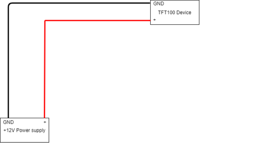
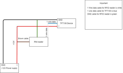
1. Connect your TFT100 device to power supply
- VCC +12V cable on the positive contact of the power supply
- Black wire on GND of the power supply
2. Connect your device to PC and open TFT100 configurator software to configure required fields for Immobilizer scenario.
You need to configure your device to read iButton/RFID card data and set immobilizer settings correctly.
Immobilizer scenario configuration
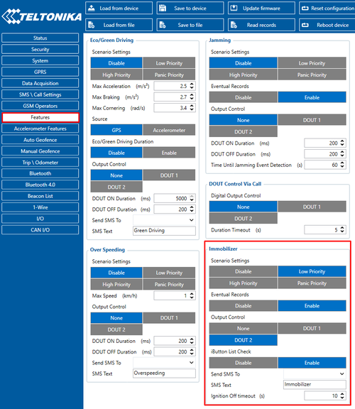
Figure 1. TFT100 Immobilizer scenario configuration
Navigate to Features panel, locate Immobilizer feature and configure Immobilizer settings as shown in the Figure 1.
1. Scenario settings – When low priority event is triggered, device makes additional record with indication of event cause.
2. Eventual Records - Select "Enable". When "Enable" value is selected, scenario status will be sent to your server only when it is triggered.
3. Output Control - you need to select which DOUT will be activated. In this case Digital output 2 will be activated if event happens.
4. iButton List Check – this parameter lets the user use this scenario for authorization.
System panel configuration
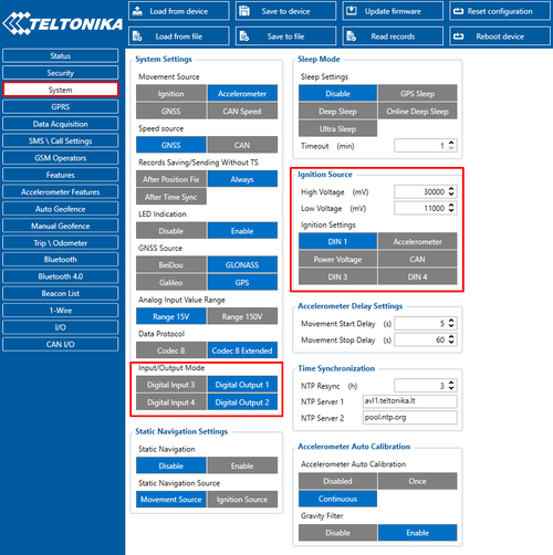
Figure 2. Ignition source configuration
Go to system tab and look at the Ignition Source and Input/Output mode sections. In Figure 2 you can see following settings:
1. Input/Output mode – Choose Digital Output which you will use in scenario. In this case Digital output 2 is enabled. If you enable digital output 1 and digital output 2, then digital input 3 and 4 will not be available.
2. Ignition source – here you need to specify boundaries between High and Low Voltage. In this case your ignition will be detected if voltage is between 11V and 30V.
3. Ignition settings – We recommend to use DIN 1 as ignition source for this scenario.
iButton configuration
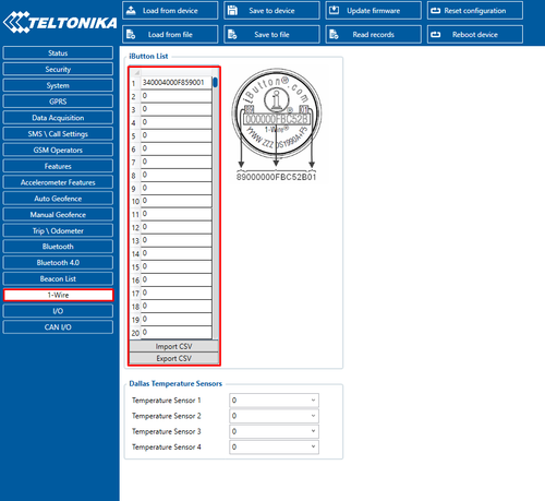
Figure 3. iButton List configuration
Go to 1-Wire settings tab. There you can see iButton list which is used to enter authorized iButton ID codes. Codes are used to authenticate user in immobilizer scenario as shown in Figure 3. For example, if you enter the wrong RFID card ID here, you will not be able to deactivate configured digital output. Below you will see a guide for RFID card ID decoding.
How to decode RFID Card ID with Configurator
1. Connect the device with RFID Card Reader to the computer using USB cable and open configurator.
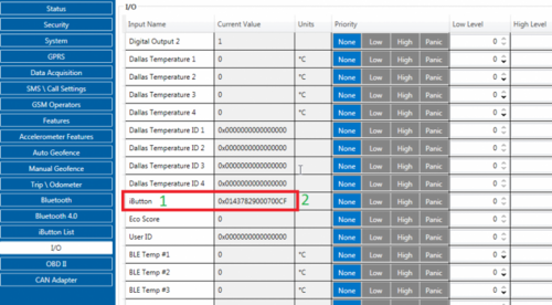
2. In the configurator, open „I/O“ tab and find iButton in the list (No 1)
3. Attach the RFID card to the RFID Card Reader and check what ID is generated under „Current Value“ column near iButton parameter. (No 2)
Figure 4. iButton ID detection
4. In our case, the generated ID when we attach the card is: 01437829000700CF. (No 2)
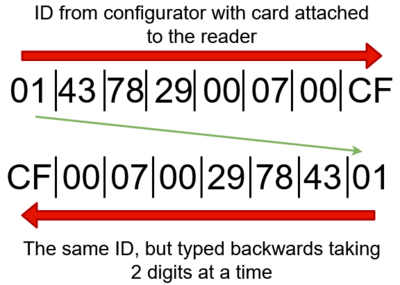
5. To get the RFID Card ID in a proper format for list checking, type the ID from the back to front taking 2 digits at a time. (Figure 5.)
Figure 5. iButton ID decoding
6. The ID we get from Figure 5 (CF00070029784301) is the ID of our RFID Card that we need to use in iButton List. Enter the ID in iButton list.
Stage 2. Connecting device to relay and iButton/RFID reader
Pinout colours for TFT100 can be found here.
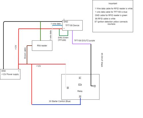
Connect power supply, TFT100, 12V Relay and RFID reader as shown in Figure 6.
1. Make sure your power supply is at 12V, then turn the power supply off.
2. Connect TFT100 to you power supply:
- Connect TFT positive cable to positive power supply contact (red wire).
- Connect TFT GND cable to GND power supply contact (black wire).
- Connect TFT DIN1 (Green) cable to positive power supply contact (red wire) in order to simulate Ignition 0/1.
3. Take relay, and connect wires in this order:
- 86 (White wire) connects to 12V cable (both, TFT100 and power supply)
- 85 Dout (Black) connects to DOUT 1 or 2 of TFT100 (in this instructions we will use DOUT2 purple cable)
4. Take iButton or Rfid card reader and connect their wires in this order. (in this case we use RFID card reader)
- Green cable connects to GND cable of TFT100 and power supply.
- Brown cable connects to 12V cables, TFT100, power supply and Relay.
- White cable connects to 1-wire (blue) of TFT100
Figure 6. Immobilizer scenario scheme
5. Connect micro USB cable to TFT100 and your computer.
6. Turn on your power supply at 12V.
7. Connect Blue cable of relay (30 starter control) to positive power supply contact using additional cable.
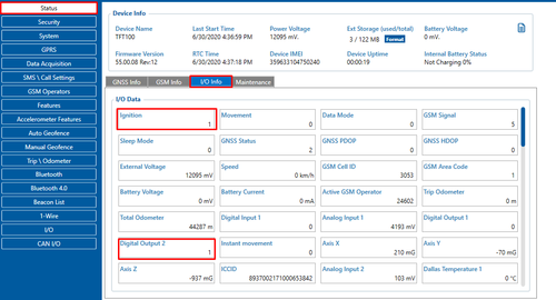
8. Open the configurator and go to status window I/O info section. In Figure 7 you can see Ignition value is 1 and digital output 2 value is also 1, digital input 1 value should be 0 (if you connect relay to DOUT 1, then you will see the value in Digital output 1 section).
Figure 7. I/O info. Ignition
In figure 7 you can see Ignition value is 1 and Digital output 2 value is also 1, digital input value should be 0 (if you connect relay to DOUT 1, then you will see the value in Digital output 1 section).
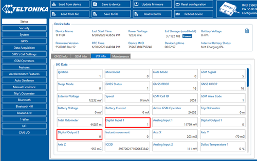
9. Touch RFID card with the RFID Card reader, and after that in the configurator status window you should see that Digital output 2 changed it’s it’s value to 0 ant digital input changed it’s value to 1. As shown in Figure 8.
Figure 8. I/O info. Digital Input
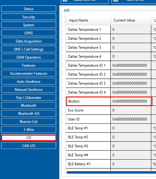
10. To check if your RFID card reader or iButton works you can go to I/O window and find iButton parameter as shown in Figure 9.
Figure 9. iButton ID
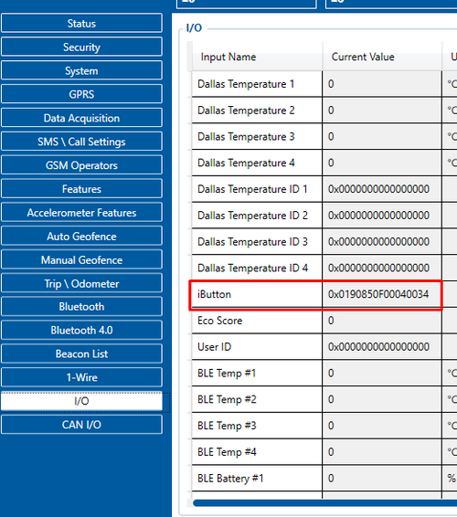
When you touch the RFID card (or iButton) to RFID card (or iButton) reader these parameters should change to your iButton’s ID:
Figure 10. iButton ID
Operation example:
When DOUT 2 value is 1, ignition is blocked and the vehicle will not be started. When the iButton/RFID card is attached to the reader, DOUT 2 value changes from 1 to 0 allowing you to start the transport normally.
