It reads can-bus data through the isolation of wires without damaging them and forwards signals to the tracking device.
Features
ECAN01 collects vehicle data from CAN bus without damaging the wires
Powered from an on-board power source
Reads the signals through the isolation of CAN bus wires
Easy to install and operate
Technical features
PARAMETER
VALUE
Minimum
Typical
Typical
Maximum
Unit
Supply Voltage
Supply Voltage (Recommended Operating Conditions)
+10
+12
+24
+30
V
Current Consumption
Working Mode
6.9
mA
Sleep Mode
1.2
mA
Operating Temperature
Operating Temperature
-25
+85
°C
Protection
Internal resettable fuse (max 33 V)
750
mA
Dimensions 39.8 x 18 x 16.7 mm
CAN-BUS speeds up to 500 kb/s
Fuse is protecting devices from high current peaks. If the voltage exceeds 33V (i.e. 35V) then protection diode stabilizes device voltage to 33V and the current value will increase accordingly.
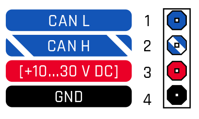
Pinout
PIN NUMBER
PIN NAME
DESCRIPTION
1
CAN L
(Blue) Connect to CAN L input of CAN BUS converter
2
CAN H
(White/Blue) Connect to CAN H input of CAN BUS converter
3
VCC
(RED) Power supply (10-30) V DC (+)
4
GND (-)
(Black) Ground wire (10-30) V DC (-)
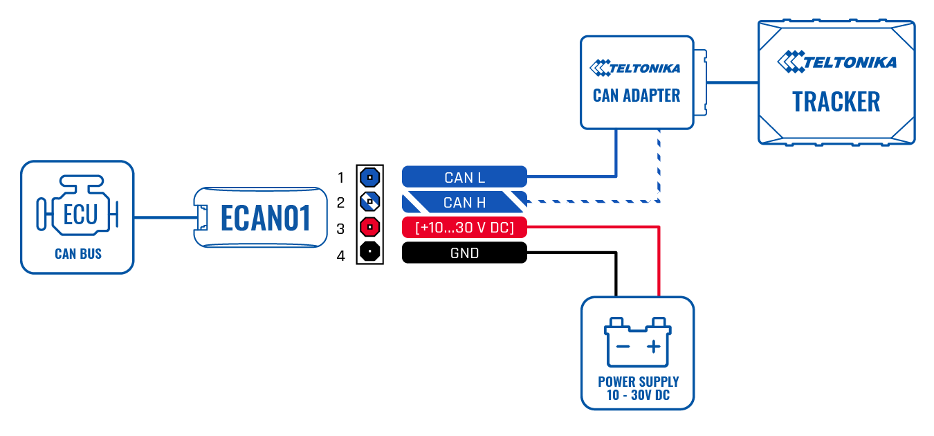
Wiring scheme
Set up ECAN01
Gently open ECAN01 cover using plastic pry tool from both sides
Insert CAN wires as shown in figure 2. Please make sure that correct slots are used (CAN High/CAN Low)