FM36M1 Features settings
Scenarios settings
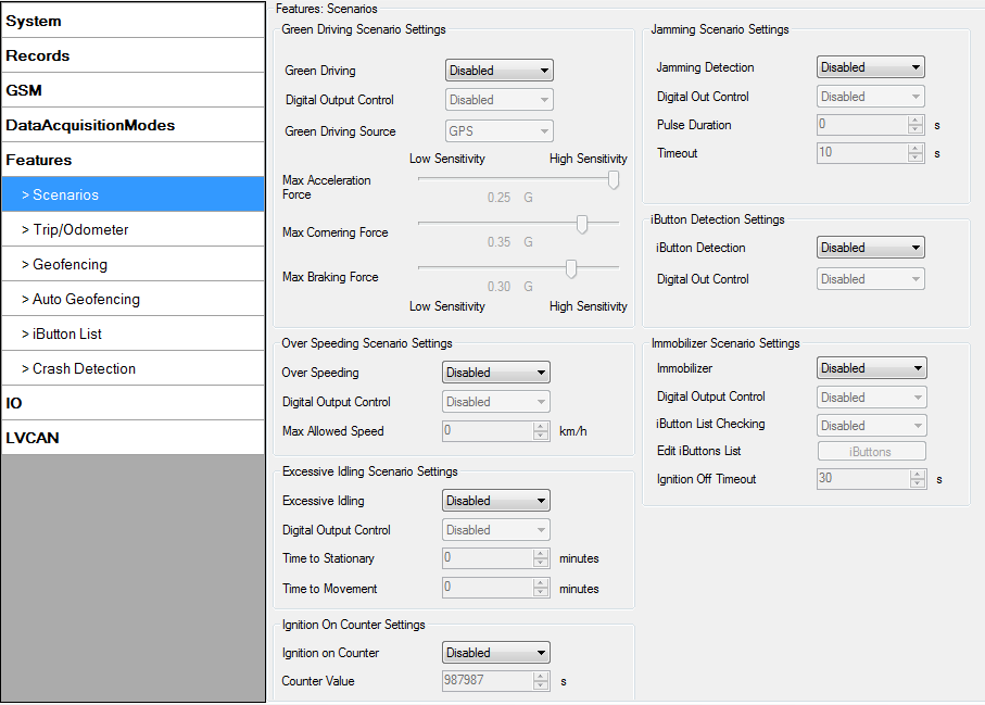
In Scenarios window six different scenarios are available: Green driving, Over Speeding, Excessive Idling, Immobilizer, iButton List checking and Jamming. All scenarios can use DOUT together, but if DOUT1 is assigned to Immobilizer, other scenarios can’t control it.
Digital Output (open drain grade) usage in scenarios:
- Green Driving
- Over Speeding
- Excessive Idling Detection
- Jamming detection
- Authorized driving
- Immobilizer
- Ignition On Counter
Green Driving
Helps to prevent and inspect driver about harsh driving. Scenario continuously monitors: accelerating force, braking force and cornering angles. Warns driver if needed. DOUT1 or DOUT2 is controlled by scenario for user needs, for example buzzer or LED.
To save 3G(in FM36M1 4G)/GPRS traffic Green Driving event will be generated (included into sent records) only when measured values are higher than those set in configuration, without additional I/O settings.
To prevent generating false events, harsh acceleration and harsh braking is monitored only when following conditions are fulfilled:
- Ignition is ON (DIN1 = 1)
- Vehicle speed is equal or higher than 10km/h
Harsh cornering is monitored only when following conditions are fulfilled:
- Ignition is ON (DIN1 = 1)
- Vehicle speed is equal or higher than 30km/h
Digital output control:
DOUTX (selected digital output) is ON for:
- 3sec. if detected value is over (0; 30] % from preconfigured allowed value;
- 5sec. if detected value is over (30; 50] % from preconfigured allowed value;
- 7sec. if detected value is over (50; -] % from preconfigured allowed value.
After period of time DOUTX is turned OFF.
Over Speeding
Helps to prevent from exceeding fixed speed and inspects driver if needed. DOUT1 or DOUT2 is controlled by scenario for user needs, to manage buzzer, LED, etc.
Digital output control:
DOUTX (selected digital output) is ON, while vehicle speed exceeds parameter value. DOUTX is activated until current speed decreases below parameter value.
Excessive Idling Detection
Scenario informs you if your vehicle is stationary but engine is on for selected period of time to help you to save fuel.
If ignition is ON and no movement, event will be generated when TMO reached. User can enable this functionality, select timeouts for stationary time and for movement time.
Jamming detection
Radio jamming is the (usually deliberate) transmission of radio signals that disrupt communications by decreasing the signal to noise ratio. When jamming detection is enabled, FM36M1 informs (with buzzer or LED, connected to digital output) driver about jamming event.
Digital output control:
DOUTX (selected digital output) is ON, while modem is fixing radio frequency jamming. After jamming is over, DOUTX is deactivated.
Authorized driving
Gives ability to use vehicle for 500 specific iButton owners (specified in iButton list). DOUT2 or DOUT1 is controlled by scenario for user needs, to manage buzzer, LED, etc.
| Note: In order for Authorized driving to work properly, at least 1 iButton ID must be written to the iButton list. |
Digital output control:
DOUTX (selected digital output) is continuously OFF. DOUTX turns ON if Ignition turns ON (configured Ignition Source=1). After authorizing iButton (iButton ID is read and it matches the ID from the iButton list), DOUT2 turns OFF. After successful authorization ignition can be turned OFF (configured Ignition Source =0) for no longer than 30 seconds, otherwise authorization must be repeated.
Immobilizer
Vehicle can be used only if iButton is connected. In this scenario iButton list is not used, connect any iButton to pass Immobilizer security. DOUT2 or DOUT1 is controlled by scenario for user needs, to manage buzzer, LED, etc.
Digital output control:
DOUTX (selected digital output) is continuously OFF. DOUTX turns ON if Ignition turns ON (configured Ignition Source = 1). After iButton ID is read (any iButton is attached), DOUTX turns OFF. After iButton identification, ignition can be turned OFF (configured Ignition Source = 0) for no longer than 30 seconds, otherwise immobilizer must be repeated.
Ignition On Counter
Ignition On Counter calculates how long Ignition was turned ON. The scenario depends on the configured Ignition source. The scenario is enabled it will count Ignition ON (logic 1) time (in seconds). After ignition OFF and ON again Horometer value will continue counting (from the last value). After the device restart, Ignition On Counter value is not restarted.
Trip and Odometer settings
Virtual Odometer
Virtual odometer is used to calculate traveled distance in FM36M1 as a separate I/O element. When FM36M1 detects movement, it starts counting distance using GNSS signal: every second it checks current location and calculates distance between current and previous point. It keeps adding these intervals until it is time to make a record, then FM36M1 records its location and adds odometer value, which is equal to the sum of all distances, measured every second. When record is made, odometer resets to zero and distance calculation starts all over again. Virtual odometer as an I/O element can be also used with Trip.
Trip
Trip customizable feature enables user extended monitoring of performed trips (from engine start at present location to engine stop at arrived location), log their start and stop points, view driven total distance. Event will be generated (included into send records) only when trip starts and finishes. This feature is available on all FM36M1 hardware versions without limitations.
| Note: Scenarios and Trip features are activated (DOUTs are activated) only if DIN1 = 1 (ignition is on). |
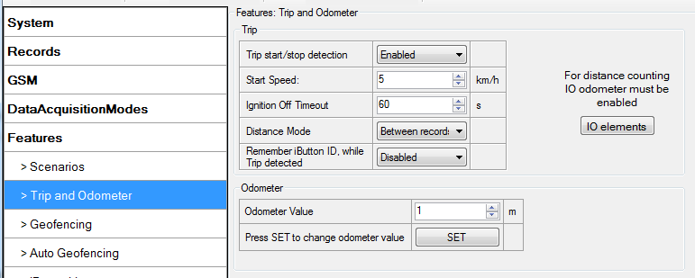
Trip window offers user to configure Trip feature. If Trip is enabled configuration of parameters are enabled.
Start Speed – GNSS speed has to be greater than the specified Start Speed in order to detect Trip Start.
Ignition Off Timeout – timeout to wait if ignition was off, to detect Trip stop.
Distance Mode – Between records, Continuous trip or Continuous can be chosen. For this feature I/O Odometer must be enabled (see Figure above).
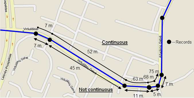
If I/O Odometer is enabled and Distance Mode variable is set to “Continuous trip”, Trip distance is going to be counted continuously (from Trip start to Trip stop). This value is written to I/O Odometer value field. When Trip is over and next Trip begins, Odometer value is reset to zero. When the next trip starts counting continuously starts from the beginning again.
If I/O Odometer is enabled and Distance Mode variable is set “Between records”, then the distance is going to be counted only between every record made. This value is written to I/O Odometer value field and reset to zero every new record until Trip stops.
If I/O Odometer is enabled and Distance Mode variable is set “Continuous”, 'Trip distance is going to be counted continuously (Starting from trip start, trip distance is saved to flash memory, see Figure below).
Continuous Odometer Value – gives ability to set starting value of the “Continuous” trip.
Remember iButton ID – devices remembers connected iButtons id(While trip is detected) and sends it to server along with periodical records.
Geofencing settings
Geofence
Geofencing is another feature which is highly customizable and can detect wherever car enters or leaves customized areas.
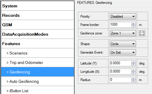
FM36M1 has 5 configurable Geofence zones and it can generate an event when defined Geofence zone border is crossed.
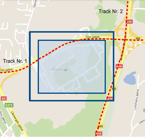
Frame border – frame border is an additional border around Geofence zone. It is additional
area around defined zone used to prevent false event recording when object stops on the border
of the area and because of GNSS errors some records are made inside area and some – outside.
Event is generated only when both borders are crossed. See figure below for details: track 1 is
considered to have entered the area while track 2 is not.
Geofencing option can be configured by following parameters visible in Figure below.
Shape – can be rectangle or circle;
Priority – priority of Geofence event: low, high or panic. These levels define priority of event information sending to server. See I/O element description for more details about priorities;
Generate event (On entrance, On exit, On Both) – choose when record will be generated;
X1 – geofence zone left bottom corner X coordinate (longitude);
Y1 – geofence zone left bottom corner Y coordinate (latitude);
X2 or R – geofence zone upper right corner X coordinate (longitude) or radius of circle when Circular zone is used (radius in meters);
Y2 – geofence zone upper right corner Y coordinate (latitude);
Autogeofence
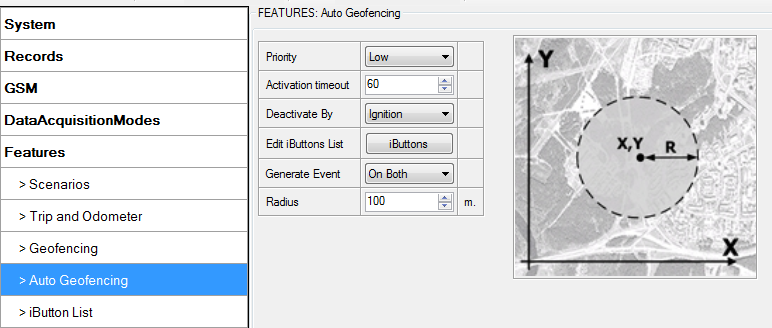
Auto Geofencing feature if enabled is activated automatically by turning off car ignition. Next time before driving user has to disable Auto Geofencing with iButton or by turning on car ignition. In case of theft car leaves Auto Geofencing zone without authorization high priority record to AVL application is sent automatically.
AutoGeofencing settings
AutoGeofence – the last known position after movement = off. If your car’s being taken away – you can be notified. The shape and size of the geofence zones are parameters. When object will leave geofence zone device will trigger an asynchronous message.
AutoGeofencing option can be configured by following parameters visible in Figure below.
Activation TMO – Time period before Geofence is activated after vehicle stops.
Deactivate By:
- Ignition – If ignition (configured Ignition Source) becomes high it will disable AutoGeofenze Zone.
- iButton – if iButton is attached it will disable AutoGeofence Zone. Edit iButton List – if list is not empty, attached iButton is tested against an iButton list, if match is found AutoGeofence zone is disabled.
Priority – Priority of generated event, which will be applied to saved record.
Exit Event – Event generation on Geofence exit.
On Both – Event generation on Geofence exit.
Note that AutoGeofencing does not require entering coordinates, instead it requires GNSS visibility. If vehicle stopped and activation timeout has passed, an AutoGeofence will be created around vehicle’s last position with set Radius value. AutoGeofence event generation works the same as Geofencing mentioned above.
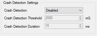
Crash Detection
If Crash Detection is enabled, it monitors acceleration on each axis which helps to detect an accident. Threshold and Duration values are set depending on the impact magnitude that is required to be detected. FM36M1 can detect events ranging between a slight tapping on the device and a severe accident. Crash Detection has AVL_ID of 247 with values of 0 - Crash Not detected and 1 - Crash Detected. If Crash Detection is enabled, AVL_ID of 247 will be saved to periodical record as LOW priority event.
