BASIC TRACK & TRACE
Introduction
Nowadays, when smart devices are progressing very fast, the phrase “basic track and trace” has a new meaning. Getting only the coordinates from the device is not enough anymore. Therefore, GPS trackers must be universal to meet various requirements. Among other things, when choosing a GPS tracker, it is very important to understand what additional services and tools you will get with the device.
Solution description
Teltonika GPS trackers are developed on one common firmware platform, which is constantly being developed and extended with new features. A common platform means that the main core of functionality is the same on all types of our trackers – be it professional, advanced or simple tracker. Smart usage of functions opens for a user various possibilities and brings a valuable advantage comparing to other GPS trackers of a similar price range in the market, making them suitable for different telematics solutions.
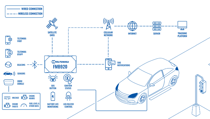
For a fast and easy “Teltonika data protocols” implementation, data packets parser tool and source code examples of communication server are prepared. For an easy control of the whole fleet, customers get access to FOTA WEB service for free. FOTA WEB is a powerful tool for remote configuration and firmware updates. Trackers support universal configurator – a tool for configuration, firmware updates and testing.
The basic firmware functionality supports such generic features like sleep modes, trip detection, and different data acquisition modes that depend on ignition/movement source or even the connected GSM operator. The device supports different ignition detection modes, depending on the installation variant. Moreover, it supports such advanced functions like auto geofence, towing detection, green driving, crash event detection, virtual odometer, unplug detection, GPRS/SMS notifications and many more. The user can easily enable the function he needs using the configurator or FOTA WEB and change the configuration in accordance with the changing needs of the client.
Teltonika trackers also support BLE technology that significantly expands their functionality. For example, if a client wants to get more telemetric vehicle data, it is possible to connect via Bluetooth® OBDII dongle and read such data like millage, engine hours, engine faults, fuel level, etc. Advanced BLE mode lets to configure BLE beacons and various BLE sensors (temperature, humidity, movement, etc.). BLE beacons can be used as an immobilizer or for the authentication of drivers and passengers. Another possible way of using them is to monitor assets during transportation, even for indoor tracking. By the way, it also is possible to configure a device via Bluetooth®. Teltonika provides Bluetooth® communication protocols so that users could develop their own mobile application to read notifications in real time and do many other useful functions with their trackers.
What you need for a solution?
- FMx920 device (FMB920 is taken as example) a simple tracker with a basic set of functions.
| Other devices that work with this solution: |
| FMB965, FMC920, FMB003, FMB001, FMC003, FMM920, FMM003, FMB002, FMB020 |
- The SIM card in order to get data to your server
- EYE BEACON/SENSOR BLE sensors that can be additionally connected if necessary
- Bluetooth® OBD II dongles Bluetooth® OBD II dongles from other manufacturers can be connected if necessary to receive data from the OBD connector
- FOTA WEB to remotely send the configuration to the device
Installation
It’s important to hide the tracker, so it would not be a simple task for the thieves to find and unplug it. But also, please do not forget to follow mounting recommendations as well.
Although devices have high gain antennas it’s important to mount devices with stickers on top and in metal-free space. The device should be firmly fixed to the surface or cables. Please make sure, that device is not fixed to heat emitting or moving parts.
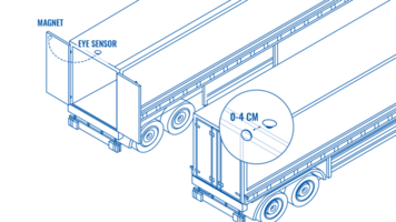
Additional accessories such as EYE SENSOR or EYE BEACON can be used for this solution. EYE SENSOR can transmit to the tracker parameters such as temperature, humidity, angle, movement, data on the presence of a magnetic field. EYE SENSOR and EYE BEACON can transmit a unique identification number, which can be used in many scenarios, such as an immobilizer, more details here. Also, check more detailed information about EYE SENSOR and EYE BEACON here and here.
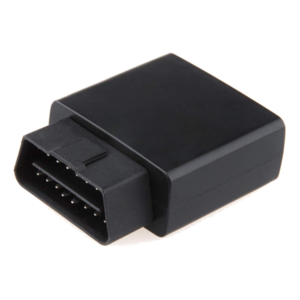
You can also use third-party OBD BT dongles for this solution (if there is a need to get data from the vehicle's OBDII interface. You can read more about selecting the appropriate OBD BT dongle models here.
Configuration
1. Prerequisites:
1.1. Read through First start guide
1.2. Understanding of possible Sleep modes.
2. BASIC TRACK & TRACE configuration:
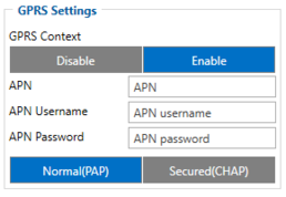
Parameter ID – Parameter name GPRS settings:
- 2001 – APN
- 2002 – APN username (if there are no APN username, empty field should be left)
- 2003 – APN password (if there are no APN password, empty field should be left)
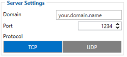
Server settings:
- 2004 – Domain
- 2005 – Port
- 2006 – Data sending protocol (0 – TCP, 1 – UDP)
After successful GPRS/SERVER settings configuration, FMB920 device will synchronize time and update records to the configured server. Time intervals and default I/O elements can be changed by using Teltonika Configurator or FMB920 Parameter list|SMS parameters.
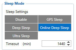
Sleep settings:
- 102 – Sleep settings(0 – Disable, 1 – Gps sleep, 2 – Deep sleep, 3 – Online Deep sleep, 4 – Ultra sleep)
Note: This scenario will not work with Deep Sleep and Ultra Sleep modes, since they disable the device's GSM module to save power.
Can adapter settings:
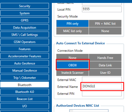
- 807 – OBDII mode (This setting enables the BT module in ODBII mode)
- 805 – This field contains the name of the device to which the tracker will connect via the BT channel
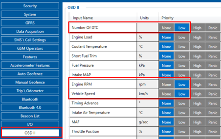
- 40100 – Number Of DTC, Priority "Low" (0 – Disabled 1 – Low 2 – High 3 – Panic )
- 40160 – Engine RPM, Priority "Low" (0 – Disabled 1 – Low 2 – High 3 – Panic )
- 40170 – Vehicle Speed, Priority "Low" (0 – Disabled 1 – Low 2 – High 3 – Panic )
Quickstart: From default configuration to BASIC TRACK & TRACE solution in one SMS:
" setparam 2001:APN;2002:APN_user;2003:APN_password;2004:Domain;2005:Port;2006:0;102:3;807:2;805:DONGLE;40100:1;40160:1;40170:1"
This SMS will set up your device to report the BASIC TRACK & TRACE scenario to the server and the possibility receive data when using OBDII BT dongle.
Note: Before SMS text, two space symbols should be inserted if no SMS username or password was set in SMS \ Call settings.
To use EYE SENSOR sensors, it is best to use the Teltonika configurator, as it becomes necessary to select the correct preset.
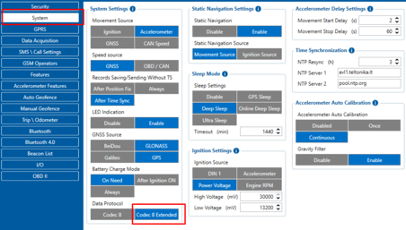
- Set the Data Protocol setting to Codec 8 Extended
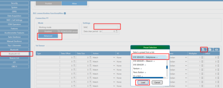
- In the Bluetooth® 4.0 section, set the operating mode for one of the 4 sensors as Advanced
- Enter the MAC address of the sensor
- Select the appropriate preset and load it
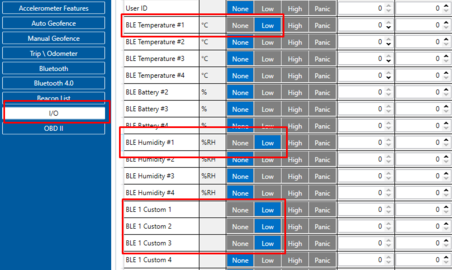
- In the I / O section, select the sensor parameters of interest: these can be temperature, humidity, motion sensor, magnetic field sensor, tilt angle sensor, sensor battery level.
Parsing information
1.Prerequisites:
1.1. Open TCP/UDP port
1.2. Read Java parser first start guide
2. Parsing example:
| Unparsed received data in hexadecimal stream |
|---|
| 00 00 00 00 00 00 00 32 8E 01 00 00 01 7E 06 5D E1 B8 00 00 00 00 00 00 00 00 00 00 00 00 00 00 00 00 00 00 00 C0 00 06 00 EF 00 00 F0 00 00 01 01 00 B3 01 00 1E 00 00 25 00 00 03 00 19 00 7D 00 56 03 25 00 24 03 84 00 00 00 03 01 4B 00 00 00 00 00 00 00 H7 01 CF 00 00 00 00 00 00 0C CB 01 D0 00 00 00 00 00 0B FF C7 00 00 01 00 00 79 3F |
| AVL Data Packet Part | HEX Code Part |
|---|---|
| Zero Bytes | 00 00 00 00 |
| Data Field Length | 00 00 00 32 |
| Codec ID | 8E (Codec 8 Extended) |
| Number of Data 1 (Number of Total Records) | 01 |
| Timestamp | 00 00 01 7E 06 5D E1 B8 |
| Priority | 00 |
| Longitude | 00 00 00 00 |
| Latitude | 00 00 00 00 |
| Altitude | 00 00 |
| Angle | 00 00 |
| Satellites | 00 |
| Speed | 00 00 |
| Event IO ID | 00 00 |
| N of Total ID | 00 C0 |
| N1 of One Byte IO | 00 06 |
| 1’st IO ID | 00 EF (AVL ID 239, Name: Ignition) |
| 1’st IO Value | 00 |
| 2’nd IO ID | 00 F0 (AVL ID 240, Name: Movement) |
| 2’nd IO Value | 00 |
| 3’rd IO ID | 00 01 (AVL ID 1, Name: Digital Input 1) |
| 3’rd IO Value | 01 (Digital Input 1 state 1 - Digital Input 1 on) |
| 4’th IO ID | 00 B3 (AVL ID 179, Name: Digital Output 1) |
| 4’th IO Value | 01 (Digital Output 1 state 1 - Digital Output 1 on) |
| 5’th IO ID | 00 1E (AVL ID 30, Name: Number of DTC) |
| 5’th IO Value | 00 (Number of DTC state 0 - without DTC) |
| 6’th IO ID | 00 25 (AVL ID 37, Name: Vehicle Speed) |
| 6’th IO Value | 00 (Vehicle Speed 0 ) |
| N2 of Two Bytes IO | 00 03 |
| 1’st IO ID | 00 19 (AVL ID 25, Name: BLE Temperature #1) |
| 1’st IO Value | 00 7D (Temperature value 1.25 degrees Celsius) |
| 2’nd IO ID | 00 56 (AVL ID 86, Name: BLE Humidity #1) |
| 2’nd IO Value | 03 25 (Humidity 80.5%) |
| 3’rd IO ID | 00 24 (AVL ID 36, Name: Engine RPM) |
| 3’rd IO Value | 03 84 (Engine RPM state 900 RPM) |
| N4 of Two Bytes IO | 00 00 |
| N8 of Two Bytes IO | 00 03 |
| 1’st IO ID | 01 4B (AVL ID 331, Name: BLE 1 Custom #1) |
| 1’st IO Value | 00 00 00 00 00 00 00 H7 (Flags. Each set bit (0-7) means the presence of value (0-7).) |
| 2’nd IO ID | 01 CF (AVL ID 463, Name: BLE 1 Custom #2) |
| 2’nd IO Value | 00 00 00 00 00 00 0C CB (Movement status) |
| 3’rd IO ID | 01 D0 (AVL ID 464, Name: BLE 1 Custom #3) |
| 3’rd IO Value | 00 00 00 00 00 0B FF C7 (Angle. 0B – Most significant byte represents device pitch. FFC7– Two least significant bytes represent device roll.) |
| NX of X Byte IO | 00 00 |
| Number of Data 2 (Number of Total Records) | 01 |
| CRC-16 | 00 00 79 3F |
