|
|
| (23 intermediate revisions by 6 users not shown) |
| Line 1: |
Line 1: |
| − | {{Template:FMB96X First start card|model=FMB964|description=Special and smart tracker with wide power supply range and high capacity internal Li-ion battery|without_battery= | + | {{Template:FMB964_First_start_card|model=FMB964}} |
| − | |pic=[[File:Fmb964.png|425px|right]]
| |
| − | }} | |
| − | | |
| − | =='''Pinout'''==
| |
| − | | |
| − | {| class="wikitable"
| |
| − | |+
| |
| − | ! style="width:10%; border: 1px solid white; border-bottom: 2px solid #0054A6; background: white; color: #0054A6; text-align: left;"| PIN NUMBER
| |
| − | ! style="width:15%; border: 1px solid white; border-bottom: 2px solid #0054A6; background: white; color: #0054A6; text-align: left;"| PIN NAME
| |
| − | ! style="width:25%; border: 1px solid white; border-bottom: 2px solid #0054A6; background: white; color: #0054A6; text-align: left;"|
| |
| − | DESCRIPTION
| |
| − | |-
| |
| − | | style="border: 1px solid white; border-bottom: 2px solid #E8E8E8; text-align: left; vertical-align: center; background: white;" | 1
| |
| − | | style="border: 1px solid white; border-bottom: 2px solid #E8E8E8; text-align: left; vertical-align: center; background: white;" | <span style=color:#FF0000>'''VCC'''</span> (6-30)V DC (+)
| |
| − | | style="border: 1px solid white; border-bottom: 2px solid #E8E8E8; text-align: left; vertical-align: center; background: white;" | Power supply (6-30) V DC (+).
| |
| − | |-
| |
| − | | style="border: 1px solid white; border-bottom: 2px solid #E8E8E8; text-align: left; vertical-align: center; background: white;" | 2
| |
| − | | style="border: 1px solid white; border-bottom: 2px solid #E8E8E8; text-align: left; vertical-align: center; background: white;" | <span style=color:#000000>'''GND''' </span>(-)
| |
| − | | style="border: 1px solid white; border-bottom: 2px solid #E8E8E8; text-align: left; vertical-align: center; background: white;" | Ground.
| |
| − | |-
| |
| − | | style="border: 1px solid white; border-bottom: 2px solid #E8E8E8; text-align: left; vertical-align: center; background: white;" | 3
| |
| − | | style="border: 1px solid white; border-bottom: 2px solid #E8E8E8; text-align: left; vertical-align: center; background: white;" | <span style=color:#D8D800>'''DIN 1'''</span>
| |
| − | | style="border: 1px solid white; border-bottom: 2px solid #E8E8E8; text-align: left; vertical-align: center; background: white;" | Digital input, channel 1. DEDICATED FOR IGNITION INPUT
| |
| − | |-
| |
| − | | style="border: 1px solid white; border-bottom: 2px solid #E8E8E8; text-align: left; vertical-align: center; background: white;" | 4
| |
| − | | style="border: 1px solid white; border-bottom: 2px solid #E8E8E8; text-align: left; vertical-align: center; background: white;" | <span style=color:#3B3B3B>'''AIN 1'''</span>
| |
| − | | style="border: 1px solid white; border-bottom: 2px solid #E8E8E8; text-align: left; vertical-align: center; background: white;" | Analog input, channel 1. Input range: 0-30 V DC.
| |
| − | |-
| |
| − | | style="border: 1px solid white; border-bottom: 2px solid #E8E8E8; text-align: left; vertical-align: center; background: white;" | 5
| |
| − | | style="border: 1px solid white; border-bottom: 2px solid #E8E8E8; text-align: left; vertical-align: center; background: white;" | <span style=color:#E0E0E0>'''DOUT 1'''</span>
| |
| − | | style="border: 1px solid white; border-bottom: 2px solid #E8E8E8; text-align: left; vertical-align: center; background: white;" | Digital output. Open collector output. Max. 3,3 A DC.
| |
| − | |-
| |
| − | |}
| |
| − | | |
| − | {{Template:FMB First start config|model=FMB964|config_link=[[FMB964 Configuration|here]]|cfg_connect=Configurator_connect-FMB964.jpg|dc_voltage=6-30 V|led_status_link=[[FMB964 LED status]]|power_cable=power cable|first_time=FMB status screen-FMB964.jpg}}
| |
| − | | |
| − | {{Template:Mounting_recommendations
| |
| − | |plugged_in=
| |
| − | |FMB2_installation_instruction=
| |
| − | |FMB0_3_nominal=
| |
| − | |voltage={{{voltage|+6..+30}}}
| |
| − | |model=FMB964
| |
| − | |2x6_connector=
| |
| − | |2x6_wires=
| |
| − | |wires=
| |
| − | |FMB0_3_ignition=
| |
| − | |FMB0_precautions=
| |
| − | |FMB2_connecting_cables=
| |
| − | }}
| |
| − | | |
| − | https://teltonika-gps.com/product/fmb964/
| |
| − | | |
| − | [[Category:FMB964]]
| |
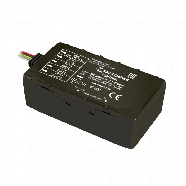
FMB964 GNSS/GSM/Blue-tooth tracker with GNSS/GSM antennas and internal battery
Quick Start Guide
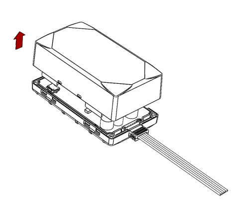
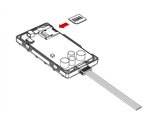
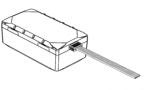
How to insert micro SIM card into FMB964
1. Remove FMB964 cover.
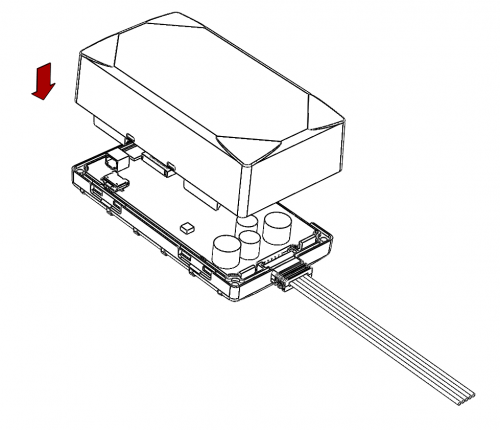
2. Insert SIM card as shown.
3. Attach cover.
4. Device is ready to be connected.
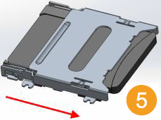
How to insert SD card into FMB964
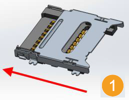
1. Push microSD card lock case.
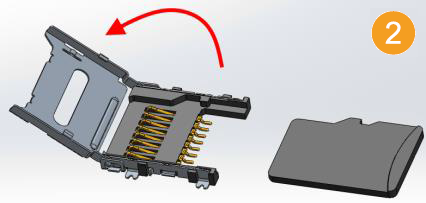
2. Open microSD card locker.
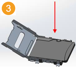
3. Correctly insert microSD card into slot.
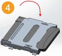
4. Close microSD card locker.
5. Push microSD card lock case to locked position.
