Here you will find instructions how to easily install and configure following CAN adapters on FMB1YX device:
Installing CAN adapter with FMB1YX device
FMB1YX has dedicated outputs for connecting CAN Adapters.
Installing LV-CAN200/ALL-CAN300/CAN-CONTROL
You can watch LV-CAN200/ALL-CAN300 installation video in our YouTube channel here or read connection instructions below.
Tools needed for installation
- LV-CAN200/ALL-CAN300/CAN-CONTROL
- Connection scheme (Please contact Teltonika Sales Representative and provide information about vehicle manufacturer, model and year.
- FMB1YX device
- Pliers
- Quick splice connectors (If vehicle CAN bus wires are very thin CAN adapter wires should be connected directly)
- Plastic pry tool
- Zip ties
Installation steps
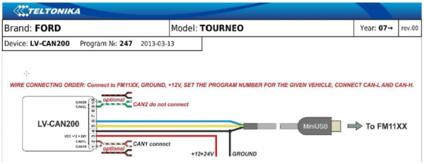
- Be ready with a vehicle connection scheme that you have received from a Teltonika Sales Representative.
- Check the scheme for the current vehicle connection. Look for connectors matching PINs numbers and colors (may be different) according to connection scheme.
- Connect CAN adapter with FMB1YX:
- Connect CAN adapter PIN 6 (Rx) to INPUT 6 of FMB1YX.
- Connect CAN adapter PIN 5 (Tx) to INPUT 6 of FMB1YX.
- Connect CAN adapter CAN wires (CAN L, CAN H) as specified in connection scheme.

Do not swap CAN L and CAN H lines.
Not all CAN adapter wires may be used in vehicle. - Connect CAN adapter positive and ground wires to the vehicle power supply lines or near FMB1YX power wires.
Do not swap power supply lines.
Make sure that voltage does not exceed 30V. - Switch vehicle ignition to ACC position. CAN adapter LED diode on the back should start blinking.
- Configure CAN adapter to read CAN bus data by setting its program number - CAN Adapter configuration

Installing LV-CAN200/ALL-CAN300 + SIMPLE-CAN
You can watch LV-CAN200/ALL-CAN300 + SIMPLE-CAN installation video in our YouTube channel here or read connection instructions below.
Tools needed for installation
- LV-CAN200/ALL-CAN300
- Connection scheme (Please contact Teltonika Sales Representative and provide information about vehicle manufacturer, model and year.
- SIMPLE-CAN (Used for contactless connection. If two CAN lines need to be connected, two SIMPLE-CAN's must be used.)
- FMB1YX device
- Pliers
- Quick splice connectors (If vehicle CAN bus wires are very thin CAN adapter wires should be connected directly)
- Plastic pry tool
- Zip ties
Installation steps
- Follow the same 1, 2, 3 installation steps as with LV-CAN200/ALL-CAN300/CAN-CONTROL installation.
- Connect the appropiate CAN bus pair of wires between CAN adapter and SIMPLE-CAN:
- If CAN1 line need to be connected as specified in connection scheme:
- Connect CAN adapter CAN1 L to CAN L of SIMPLE-CAN.
- Connect CAN adapter CAN1 H to CAN H of SIMPLE-CAN.
- If CAN2 line need to be connected as specified in connection scheme:
- Connect CAN adapter CAN2 L to CAN L of SIMPLE-CAN.
- Connect CAN adapter CAN2 H to CAN H of SIMPLE-CAN.
Do not swap CAN L and CAN H lines.
Not all CAN adapter wires may be used in vehicle.
- Fasten SIMPLE-CAN between vehicle CAN bus wires according to the connection scheme. It doeasn't matter which wire is on which side.
- Connect CAN adapter positive and ground wires to the vehicle power supply lines or near FMB1YX power wires.
Do not swap power supply lines.
Make sure that voltage does not exceed 30V. - Switch vehicle ignition to ACC position.
- SIMPLE-CAN LED will shine continously so device awaits for calibration.
If after calibration process LED shines continuously, it means that device is not calibrated yet, CAN-BUS transmission has failed or ignition during calibration was not ON. - Configure CAN adapter to read CAN bus data or control vehicle by setting its program number - CAN Adapter configuration
CAN Adapter Configuration
CAN Adapter program number selection
CAN Adapter must be set to program number which depends on the vehicle model. Needed program number is always written on CAN Adapter mounting scheme. Program number may vary depending on the Software Date of your Adapter. CAN Adapter Software date must be newer than connection scheme date to ensure proper operation. Please contact Teltonika sales manager to get the latest supported vehicle list and mounting scheme for your vehicle providing information about car manufacturer, model and year.
CAN Adapter program number configuration via SMS command
CAN Adapter program number can be set remotely, using SMS command.
SMS command:lvcansetprog Xorlogin pass lvcansetprog XX is new program number value.
Example:lvcansetprog 11434SMS response:LVCAN ProgNum: 11434CAN Adapter program number configuration via configurator
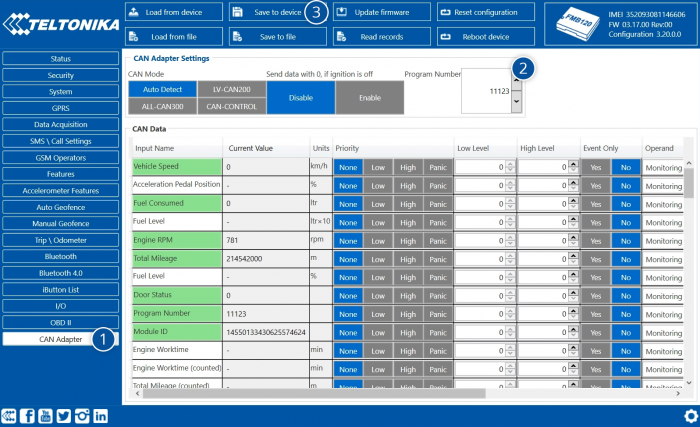
CAN Adapter program number can be set via configurator: CAN Adapter -> Program Number. When program number is entered press Save to device button that saves the entered program number into FMB1YX.
Selecting CAN Adapter program number manually
Depending on used CAN Adapter, length of setup sequence will vary.
Steps to set program number:
For
ALL-CAN300
LV-CAN200
3 digitFor
ALL-CAN300
LV-CAN200
4 digitFor
LV-CAN200
CAN-CONTROL
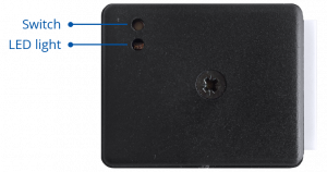
5 digit1. Hold SWITCH down until LED stars blinking. 2. Release the SWITCH. 3. Then LED starts blinking and counting first digit of program number (one blink means digit 1, two blinks mean digit 2 etc). To stop counter, push SWITCH. 4. Release the SWITCH, then LED starts blinking and counting second digit of program number. To stop counter, push SWITCH. 5. Release the SWITCH, then LED starts blinking and counting third digit on program number. To stop counter, push SWITCH. 6. Release the SWITCH, then LED starts blinking and counting fourth digit on program number. To stop counter, push SWITCH. 7. Release the SWITCH, then LED starts blinking and counting fifth digit on program number. To stop counter, push SWITCH. All Devices 8. Release SWITCH, if programming is successful LED will blink 10 times.
* LV-CAN200 length of number depends on device Software Date. Please see Adapter changes section for LV-CAN200 or ALL-CAN300 to see what length of program number to use. To determine SW Date use SMS command lvcangetinfo or connect your FMB1YX device to Configurator and find date in Status window.
FMB1YX CAN Adapter parameters configuration
Because FMB1YX have CAN Adapter RX and TX in its own pinout, device configuration can be performed via micro-USB when CAN adapter is connected to the vehicle.
When FMB1YX is connected to CAN Adapter, user can see all information that is received from the vehicle in Configurator → CAN Adapter, all data are highlighted by green background color. Information in this section is automatically refreshed. CAN bus data which can be read from your car is provided in "CAN Adapter supported vehicle" documents.
The CAN Adapter I/O element can be configured like any other I/O element in FMB configurator.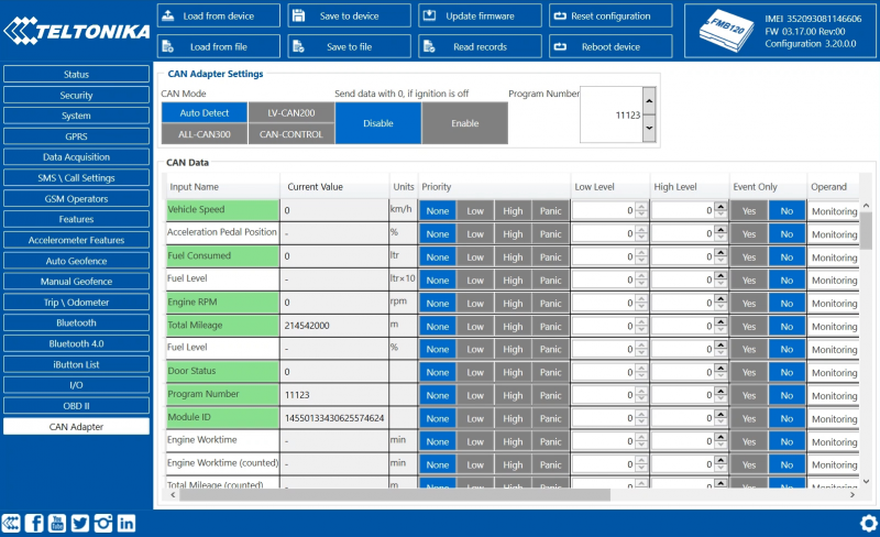
When using offline configuration method user can select which CAN data will be read from CAN Adapter and sent directly to the server without connection to adapter. Please note that parameters depend on vehicle manufacturer and vehicle model. For further information check "CAN Adapter supported cars” documents.
All information about I/O element parameters description is in section I/O settings.
All CAN Adapter parameters configuration settings are described in "FMB1YX Protocols" document, except state flag bitmasks, which are described in the table below.SMS Configuration
All CAN Adapter IO elements can be configured remotely via SMS command.
SMS/GPRS Commands
CAN Adapters have several dedicated SMS/GPRS commands. All commands are case sensitive. Essential fields in ‘SMS’ part is ‘Login’ and ‘Password’. The login and password are used with every SMS sent to FM device. If login and password are not set, in every SMS sent to FM device two spaces before command have to be used (<space><space><command>).
Command structure with set login and password:
<login><space><password><space><command>, example: asd 123 lvcangetinfo
GPRS commands require Codec 12 protocol.For more SMS commands please see SMS/GPRS command list
COMMAND DESCRIPTION RESPONSE lvcansetprog # Set program number to CAN Adapter that is connected to FMB1YX.
# - three digit number that identity vehicle.Yes lvcansimpletacho # Add or remove simpletacho start byte.
# - 0 or 1 (0 – don’t add start byte, 1 – add start byte).No lvcangetprog Get program number from CAN Adapter that is connected to FMB1YX. Yes lvcangetinfo Get information about connected CAN Adapter Yes lvcanclear # Clear Total Mileage (counted), Engine Work Time (counted), Fuel Consumed (counted) parameters values.
# - parameter (0 – Engine work time (counted), 1 – Fuel Consumed (counted), 2 – Vehicle Mileage (counted)).Yes allcanmode Turn on ALL-CAN300 mode. Yes lvcanmode Turn on LV-CAN200 mode. Yes lvcanfaultcodes Read DTC fault codes Yes CAN-CONTROL specific commands lvcanopenalldoors Open [unlock] all doors Yes lvcanclosealldoors Close [lock] all doors Yes lvcanopentrunk Open [unlock] trunk Yes lvcanturninglights One flash of all turn lights ordered trough accidental / blinking turn light switch Yes vcanwindowsopen:# open windows # sec. (one sending of command will cause the windows to continue opening for xx seconds). #: [1,3,5...25,27,29] Yes lvcanwindowsclose:# close windows # sec. (one sending of command will cause thewindows to continue closing for xx seconds). #: [1,3,5...25,27,29] Yes
CAN Adapter State Flags
CAN Adapters receive data about the states of various systems within the vehicle, and send them as flags to FMB1YX. FM device stores these flags in hexadecimal format, as one variable. Bellow is a list of kept flags and how to retrieve them. The full list is stored only by ALL-CAN300, LV-CAN200 and CAN-CONTROL store only control state and security state flags.
Property name Size, bytes Value bitmasks Control state flags 4 Byte0 (LSB):
0x01 – STOP
0x02 – Oil pressure / level
0x04 – Coolant liquid temperature / level
0x08 – Handbrake system
0x20 – AIRBAG
Byte1:
0x01 – CHECK ENGINE
0x02 – Lights failure
0x04 – Low tire pressure
0x08 – Wear of brake pads
0x10 – Warning
0x20 – ABS
0x40 – Low Fuel
Byte2:
0x01 – ESP
0x02 – Glow plug indicator
0x04 – FAP
0x08 – Electronics pressure control
0x10 – Parking lights
0x20 – Dipped headlights
0x40 – Full beam headlights
Byte3:
0x40 – Passenger's seat belt
0x80 – Driver's seat belt
Agricultural machinery flags 8 Byte0 (LSB):
0x01 – Mowing
0x02 – Grain release from hopper
0x04 – First front hydraulic turned on
0x08 – Rear Power Take-Off turned on
Byte1:
0x01 – Excessive play under the threshing drum
0x02 – Grain tank is open
0x04 – 100% of Grain tank
0x08 – 70% of Grain tank
0x10 – Drain filter in hydraulic system of drive cylinders is plugged
0x20 – Pressure filter of drive cylinders hydraulic system is plugged
0x40 – Alarm oil level in oil tank
0x80 – Pressure filter of brakes hydraulic system is plugged
Byte2:
0x01 – Oil filter of engine is plugged
0x02 – Fuel filter is plugged
0x04 – Air filter is plugged
0x08 – Alarm oil temperature in hydraulic system of chassis
0x10 – Alarm oil temperature in hydraulic system of drive cylinders
0x20 – Alarm oil pressure in engine
0x40 – Alarm coolant level
0x80 – Overflow chamber of hydraulic unit
Byte3:
0x01 – Unloader drive is ON. Unloading tube pivot is in idle position
0x02 – No operator!
0x04 – Straw walker is plugged
0x08 – Water in fuel
0x10 – Cleaning fan RPM
0x20 – Trashing drum RPM
Byte4:
0x02 – Low water level in the tank
0x04 – First rear hydraulic turned on
0x08 – Standalone engine working
0x10 – Right joystick moved right
0x20 – Right joystick moved left
0x40 – Right joystick moved front
0x80 – Right joystick moved back
Byte5:
0x01 – Brushes turned on
0x02 – Water supply turned on
0x04 – Vacuum cleaner
0x08 – Unloading from the hopper
0x10 – High Pressure washer (Karcher)
0x20 – Salt (sand) disperser ON
0x40 – Low salt (sand) level
Byte6:
0x01 – Second front hydraulic turned on
0x02 – Third front hydraulic turned on
0x04 – Fourth front hydraulic turned on
0x08 – Second rear hydraulic turned on
0x10 – Third rear hydraulic turned on
0x20 – Fourth rear hydraulic turned on
0x40 – Front three-point Hitch turned on
0x80 – Rear three-point Hitch turned on
Byte7:
0x01 – Left joystick moved right
0x02 – Left joystick moved left
0x04 – Left joystick moved front
0x08 – Left joystick moved back
0x10 – Front Power Take-Off turned on
Security state flags 8 Byte0 (LSB):
0x20 – Bit appears when any operate button in car was put
0x40 – Bit appears when immobiliSer is in service mode
0x80 – Immobiliser, bit appears during introduction of a programmed sequence of keys in the car
Byte1:
0x01 – the key is in ignition lock
0x02 – Ignition on
0x04 – Dynamic ignition on
0x08 – Webasto
0x20 – Car closed by factory's remote control
0x40 – Factory-installed alarm system is actuated (is in panic mode)
0x80 – Factory-installed alarm system is emulated by module
Byte2:
0x01 – Parking activated (automatic gearbox)
0x10 – Handbrake is actuated (information available only with ignition on)
0x20 – Footbrake is actuated (information available only with ignition on)
0x40 – Engine is working (information available only when the ignition on)
0x80 – Reverse is on
Byte3:
0x01 – Front left door opened
0x02 – Front right door opened
0x04 – Rear left door opened
0x08 – Rear right door opened
0x10 – Engine cover opened
0x20 – Trunk door opened
Byte4:
0x01 – Car was closed by the factory's remote control
0x02 – Car was opened by the factory's remote control
0x03? – Trunk cover was opened by the factory's remote control
0x04 – Module has sent a rearming signal
0x05? – Car was closed three times by the factory's remote control
- High nibble (mask 0xF0 bit)
0x80 – CAN module goes to sleep mode
Tachograph driver card presence 1 0x00 – No driver card
0x01 – Driver1 card presence
0x02 – Driver2 card presence
0x03 – Driver1 and driver2 cards present
Driver 1 states 1 0xX0 – Break/rest
0xX1 – Availability
0xX2 – Work
0xX3 – Driving
0x0X – No time-related warning detected
0x1X – Limit #1: 15 min before 4 1/2 h
0x2X – Limit #2: 4 1/2 h reached (continuous driving time exceeded)
0x3X – Limit #3: 15 minutes before optional warning 1
0x4X – Limit #4: optional warning 1 reached
0x5X – Limit #5: 15 min before optional warning
0x6X – Limit #6: optional warning 2 reached
Driver 2 states 1
Send data with 0, if ignition is off
Depending on CAN Adapter I/O parameters and ignition status, FMB1YX can send locked (last known) CAN Adapter I/O and active (real time) parameters values or reset values to 0. When ignition is off, CAN Adapter I/O parameters values sent to server are:
CAN Adapter I/O element Status Vehicle Speed reset Accelerator pedal position reset Total fuel used lock Fuel level (liters) lock Engine RPM reset Total mileage lock Fuel level (%) lock Program number lock Module ID lock Engine Work Time lock Engine Work Time (counted) lock Total Mileage (counted) lock Fuel Consumed (counted) lock Fuel Rate reset Program number lock AdBlue Level (%) lock AdBlue Level (liters) lock Engine Load reset Engine Temperature active Axle 1 Load lock Axle 2 Load lock Axle 3 Load lock Axle 4 Load lock Axle 5 Load lock Control State Flags active Agricultural Machinery Flags active Harvesting Time lock Area of Harvest reset Mowing Efficiency active Grain Mown Volume active Grain Moisture active Harvesting Drum RPM reset Gap Under Harvesting Drum active Security State Flags active Tachograph Total Vehicle Distance lock Trip Distance reset Tachograph Vehicle Speed reset Tachograph Driver Card Presence active Driver1 States active Driver2 States active Driver1 Continuous Driving Time active Driver2 Continuous Driving Time active Driver1 Cumulative Break Time active Driver2 Cumulative Break Time active Driver1 Selected Activity Duration active Driver2 Selected Activity Duration active Driver1 Cumulative Driving Time active Driver2 Cumulative Driving Time active LV-CAN200/ALL-CAN300 Important Information
Program Number logic change
Due to the growing number of supported cars, program numbers have exceeded "999". In order to maintain one number format, we are moving from 3-digit to 4-digit program numbers.
In new LV-CAN200/ALL-CAN300 firmware (from 2017-09-01) all program numbers that were up to 999 are changed to start from 1000. So that further program numbers would continue the counting with 4-digit numbers.
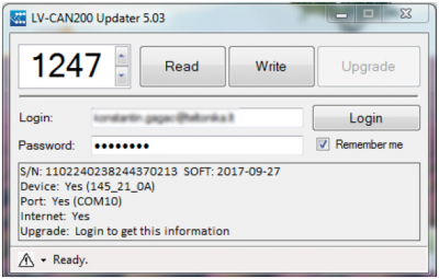
However, all existing program numbers stay the same, but "1" is added to the front. Device still understands the entered 3-digit program number (via SMS/GPRS), it will automatically add "1" before it. If you enter "247" - device number will turn into "1247". In Bootloader only 4-digit format is available, just add "1" to the front of the needed program number.Example
When using older connection schemes where program number displayed as 3-digit program number:
Using LV-CAN200/ALL-CAN300 Bootloader from soft version 2017-09-27 it is necessary to add "1" to the front of program number: