|
|
| (6 intermediate revisions by 5 users not shown) |
| Line 10: |
Line 10: |
| | *Immobilizer - prevent anyone from starting the vehicle without scanning an iButton first. | | *Immobilizer - prevent anyone from starting the vehicle without scanning an iButton first. |
| | *Authorized driving - keep track of who is driving your vehicle according to the iButton ID they use to authenticate themselves. | | *Authorized driving - keep track of who is driving your vehicle according to the iButton ID they use to authenticate themselves. |
| − | *AutoGeofencing – gives ability to know when car leaves customized areas without iButton authorization.
| + | |
| | <br> | | <br> |
| | [[File:IButton_reader.jpg|alt=|right|400x400px]] | | [[File:IButton_reader.jpg|alt=|right|400x400px]] |
| Line 19: |
Line 19: |
| | | | |
| | | | |
| − | ==Product Specification==
| + | '''Technical characteristics:''' |
| − | | |
| | | | |
| − | {| class="wikitable"
| + | *1-Wire Interface |
| − | |+
| + | *Wiring - White wire = 1-wire signal, Brown wire = Ground |
| − | ! style="width:50%; border: 1px solid white; border-bottom: 2px solid #0054A6; background: white; color: #0054A6; text-align: left;" |NAME
| + | *Case material - Plastic (polyacetal) |
| − | ! style="border: 1px solid white; border-bottom: 2px solid #0054A6; background: white; color: #0054A6; text-align: left;" |DESCRIPTION
| + | *Ring material Ferrite steel with chrome plating |
| − | |-
| + | *Signal joint material Brass with chrome plating |
| − | | style="border: 1px solid white; border-bottom: 2px solid #E8E8E8; text-align: left; vertical-align: center; background: white;" |Interface
| + | *Wire dimensions 2 wires Ø 0,25 mm2, 40 cm length |
| − | | style="border: 1px solid white; border-bottom: 2px solid #E8E8E8; text-align: left; vertical-align: center; background: white;" |1-Wire Interface
| + | *Fastening method M12 screw |
| − | |-
| + | *Operating temperature From -40 ºC to +85 ºC |
| − | | style="border: 1px solid white; border-bottom: 2px solid #E8E8E8; text-align: left; vertical-align: center; background: white;" |Wiring
| + | *Operating humidity Up to 70% |
| − | | style="border: 1px solid white; border-bottom: 2px solid #E8E8E8; text-align: left; vertical-align: center; background: white;" |White wire = 1-wire signal, Brown wire = Ground
| |
| − | |-
| |
| − | | style="border: 1px solid white; border-bottom: 2px solid #E8E8E8; text-align: left; vertical-align: center; background: white;" |Case material
| |
| − | | style="border: 1px solid white; border-bottom: 2px solid #E8E8E8; text-align: left; vertical-align: center; background: white;" |Plastic (polyacetal)
| |
| − | |-
| |
| − | | style="border: 1px solid white; border-bottom: 2px solid #E8E8E8; text-align: left; vertical-align: center; background: white;" |Ring material
| |
| − | | style="border: 1px solid white; border-bottom: 2px solid #E8E8E8; text-align: left; vertical-align: center; background: white;" |Ferrite steel with chrome plating
| |
| − | |-
| |
| − | | style="border: 1px solid white; border-bottom: 2px solid #E8E8E8; text-align: left; vertical-align: center; background: white;" |Signal joint material
| |
| − | | style="border: 1px solid white; border-bottom: 2px solid #E8E8E8; text-align: left; vertical-align: center; background: white;" |Brass with chrome plating
| |
| − | |-
| |
| − | | style="border: 1px solid white; border-bottom: 2px solid #E8E8E8; text-align: left; vertical-align: center; background: white;" |Fastening method
| |
| − | | style="border: 1px solid white; border-bottom: 2px solid #E8E8E8; text-align: left; vertical-align: center; background: white;" |M12 screw
| |
| − | |-
| |
| − | | style="border: 1px solid white; border-bottom: 2px solid #E8E8E8; text-align: left; vertical-align: center; background: white;" |Wire dimensions 2 wires
| |
| − | | style="border: 1px solid white; border-bottom: 2px solid #E8E8E8; text-align: left; vertical-align: center; background: white;" |Ø 0,25 mm2
| |
| − | |-
| |
| − | | style="border: 1px solid white; border-bottom: 2px solid #E8E8E8; text-align: left; vertical-align: center; background: white;" |Cable length
| |
| − | | style="border: 1px solid white; border-bottom: 2px solid #E8E8E8; text-align: left; vertical-align: center; background: white;" |40 cm
| |
| − | |-
| |
| − | | style="border: 1px solid white; border-bottom: 2px solid #E8E8E8; text-align: left; vertical-align: center; background: white;" |Operating temperature
| |
| − | | style="border: 1px solid white; border-bottom: 2px solid #E8E8E8; text-align: left; vertical-align: center; background: white;" |-40 ºC to +85 ºC
| |
| − | |-
| |
| − | | style="border: 1px solid white; border-bottom: 2px solid #E8E8E8; text-align: left; vertical-align: center; background: white;" |Operating humidity
| |
| − | | style="border: 1px solid white; border-bottom: 2px solid #E8E8E8; text-align: left; vertical-align: center; background: white;" |Up to 70%
| |
| − | |-
| |
| − | | style="border: 1px solid white; border-bottom: 2px solid #E8E8E8; text-align: left; vertical-align: center; background: white;" |Supported by
| |
| − | | style="border: 1px solid white; border-bottom: 2px solid #E8E8E8; text-align: left; vertical-align: center; background: white;" |<span class="mw-collapsible mw-collapsed"> [https://wiki.teltonika-gps.com/view/FMB110 FMB110], [https://wiki.teltonika-gps.com/view/FMB120 FMB120], [https://wiki.teltonika-gps.com/view/FMB122 FMB122], [https://wiki.teltonika-gps.com/view/FMB125 FMB125], [https://wiki.teltonika-gps.com/view/FMU125 FMU125], [https://wiki.teltonika-gps.com/view/FMM125 FMM125], [https://wiki.teltonika-gps.com/view/FMC125 FMC125], [https://wiki.teltonika-gps.com/view/FMB130 FMB130], [https://wiki.teltonika-gps.com/view/FMU130 FMU130], [https://wiki.teltonika-gps.com/view/FMC130 FMC130], [https://wiki.teltonika-gps.com/view/FMM130 FMM130], [https://wiki.teltonika-gps.com/view/FMB140 FMB140], [https://wiki.teltonika-gps.com/view/FMB202 FMB202], [https://wiki.teltonika-gps.com/view/FMB204 FMB204], [https://wiki.teltonika-gps.com/view/FMB640 FMB640], [https://wiki.teltonika-gps.com/view/FMC640 FMC640], [https://wiki.teltonika-gps.com/view/FMM640 FMM640] </span>
| |
| − | |-
| |
| − | |}
| |
| | | | |
| | | | |
Introduction to the product
Description:
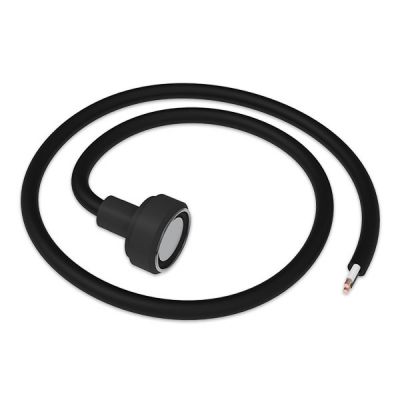
One of the implemented features for fleet management devices is 1-Wire data protocol, which can be used for iButton reading. It is the most straight-forward way to implement driver authorization in your vehicles.
1-Wire iButton readers are great in these use cases:
- Immobilizer - prevent anyone from starting the vehicle without scanning an iButton first.
- Authorized driving - keep track of who is driving your vehicle according to the iButton ID they use to authenticate themselves.
Technical characteristics:
- 1-Wire Interface
- Wiring - White wire = 1-wire signal, Brown wire = Ground
- Case material - Plastic (polyacetal)
- Ring material Ferrite steel with chrome plating
- Signal joint material Brass with chrome plating
- Wire dimensions 2 wires Ø 0,25 mm2, 40 cm length
- Fastening method M12 screw
- Operating temperature From -40 ºC to +85 ºC
- Operating humidity Up to 70%
Installation
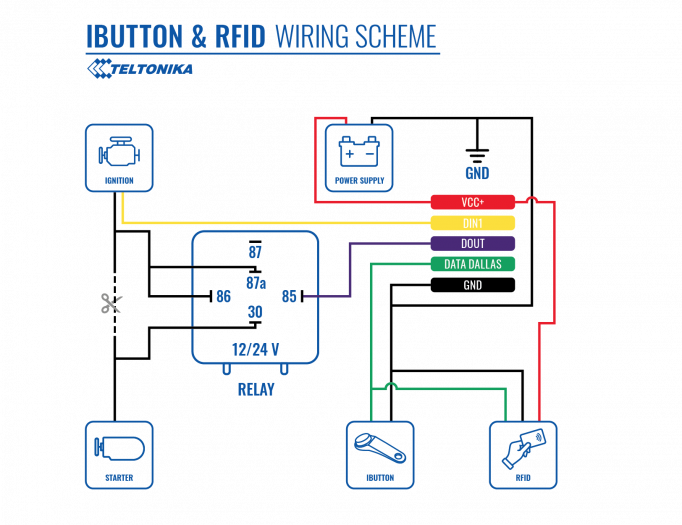
To connect the 1-wire iButton reader, simply connect the 1-Wire Signal wire from the reader to the 1-Wire Data pin on the device, and connect the ground wire to the same grounding used for the device.

| PIN NUMBER
|
PIN NAME
|
DESCRIPTION
|
| 1
|
1-wire Data (Dallas Data)
|
Sends iButton ID
|
| 2
|
GND (-)
|
Ground.
|
Device configuration
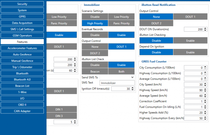
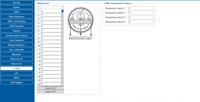
The reader works as soon as it is connected, but the iButton isn't used anywhere other than displayed in the iButton I/O element. In order to use it for the Immobilizer scenario, the device must have the scenario enabled. Then, iButton check can be enabled to only accept iButtons specified in the iButton list under the 1-Wire tab.


