Template:FMx CAN Adapters
This document describes the steps to install and configure the following CAN adapters with your Teltonika tracker:
Possible CAN Data Reading Configurations
Teltonika CAN series trackers have an integrated CAN chip which can be used to read CAN bus data directly from the vehicle. This is not discussed here, see separate pages of CAN series trackers.
CAN adapters allow expanding a non-CAN tracker’s functionality.
Additionally, you can use the contactless ECAN02 adapter when insurance limitations do not allow modification of the wiring.
To summarize, the four possible configurations to read CAN data are:
- (wired) CAN tracker
- (wired) Non-CAN tracker + CAN adapter
- (contactless) CAN tracker + ECAN02 adapter
- (contactless) Non-CAN tracker + CAN adapter + ECAN02 adapter
CAN Adapter Installation
We recommend watching the videos for an overview of CAN adapters and their installation:
- Teltonika CAN adapters Part 1: Introduction
- Teltonika CAN adapters Part 2: Installation
- Contactless CAN data reading with ECAN02
- Example installation guide with FMx150 & ECAN02
Items Required for Installation
- Connection schematic for your vehicle (contact your Teltonika sales representative and provide the required vehicle make, model and year)
- CAN adapter LV-CAN200 / ALL-CAN300 / CAN-CONTROL
- Optional: ECAN02 for contactless reading. See #Contactless Connection Using ECAN02 for separate instructions for ECAN02 installation
- {{{model}}} device
- Quick splice connectors (if the CAN bus wires of your vehicle are very thin, connect CAN adapter wires directly)
- Pliers
- Plastic pry tool
- Zip ties
Installation Procedure
NOTE! The maximal number of vehicle CAN lines that can be read depends on the number of available CAN pairs on your CAN-enabled tracker/CAN adapter.
Wired Connection to a CAN Adapter
- Prepare the connection schematic for your vehicle that you have received from your sales representative.
- On the vehicle, look for connectors matching the pin numbers and colors in the schematic (colors may not match due to differences between vehicle manufacturers).
- First, interconnect CAN adapter with {{{model}}} device. Use the available connection, depending on your device:
- RS232/RJ45 connection (only for Professional series devices)
- Connection via pins 5/6 (wire colors may differ):
- Connect CAN adapter PIN 6 (Rx) to INPUT 6.
- Connect CAN adapter PIN 5 (Tx) to INPUT 5.
- Then, connect vehicle CAN wires to the CAN adapter (CAN L, CAN H) as specified in the connection schematic.
- ATTENTION! Do not swap CAN L and CAN H lines. Not all CAN adapter wires may be used in the vehicle.
- Finally, connect positive and ground wires of CAN adapter to the power source. Ideally, connect to the same power and ground as used by the tracker. Ensure proper ground connection.
- ATTENTION! Do not swap power supply lines. Make sure that voltage does not exceed 30V.
- Switch vehicle ignition to ACC position. LED on the rear of CAN adapter should start blinking.
- Configure CAN adapter to read CAN bus data or control vehicle by setting its program number (see #CAN Program Numbers below).
NOTE! Connection schematics are shown below. These are not the connection schematics for your vehicle, but only general examples – every vehicle has a specific schematic.


Contactless Connection Using ECAN02
If you wish to read data contactlessly from several vehicle CAN lines, you will need to use equally as many ECAN02 adapters, e.g. two ECAN02 adapters for two vehicle CAN lines. This is also limited by the number of available CAN pairs on your CAN-enabled tracker/CAN adapter.
We do not recommend using ECAN02 with CAN-CONTROL, as ECAN02 can only be used for reading CAN bus data, not sending commands to the vehicle CAN bus.
The initial and final connection steps are identical to the wired connection.
- Prepare the connection schematic for your vehicle that you have received from your sales representative.
- On the vehicle, look for connectors matching the pin numbers and colors (may not match) in the schematic.
- If you are using a CAN adapter, first, interconnect CAN adapter with {{{model}}} device. Use the available connection, depending on your device:
- RS232/RJ45 connection (only for Professional series devices)
- Connection via pins 5/6 (wire colors may differ):
- Connect CAN adapter PIN 6 (Rx) to INPUT 6.
- Connect CAN adapter PIN 5 (Tx) to INPUT 5.
- Connect ECAN02 wires to your CAN adapter or CAN-enabled tracker.
- CAN L of ECAN02 to CANx L on adapter/tracker.
- CAN H of ECAN02 to CANx H on adapter/tracker.
- ATTENTION! Do not swap CAN L and CAN H lines. Not all CAN adapter wires may be used in the vehicle.
- Then, mount the ECAN02 adapter on the vehicle CAN bus wires. Do this according to the connection schematic. Make sure that CAN H and CAN L lines on the vehicle correspond to CAN H and CAN L markings on ECAN02 PCB.
- Finally, connect positive and ground wires of CAN adapter to the power source. Ideally, connect to the same power and ground as used by the tracker. Ensure proper ground connection.
- ATTENTION! Do not swap power supply lines. Make sure that voltage does not exceed 30V.
- Switch vehicle ignition to ACC position. LED on the back of CAN adapter should start blinking.
- Configure CAN-enabled tracker/CAN adapter to read CAN bus data or control vehicle by setting its program number (see #CAN Program Numbers below).
CAN Program Numbers
A CAN program is embedded software that runs on a device communicating over the CAN bus. It defines how the device processes data. A CAN program number uniquely identifies the version of this software.
Your CAN adapter must be set to the correct program number. The required program number is always given in the CAN adapter schematic.
The amount of program number digits may vary depending on the software and manufacturing date of your CAN adapter. This is because the number of supported vehicles grows significantly over time: in 2017, we moved from 3-digit to 4-digit numbers, then to 5-digit numbers in 2018; this will likely continue in the future.
Check the number of digits here:
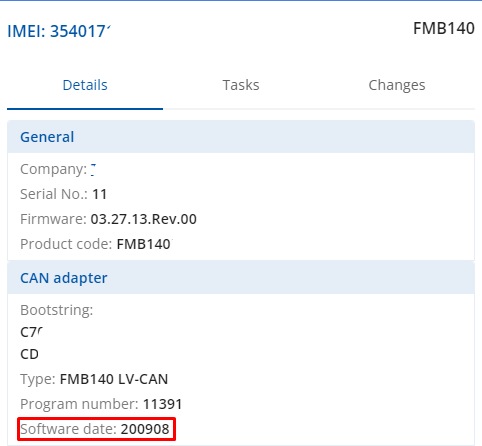
Important! To correctly set the program number, date of CAN adapter software must be the same as or newer than the connection schematic date. Check date of CAN adapter software via:
Setting CAN Program Numbers
There are three ways to set the CAN program number:
- Software (e.g. Teltonika Configurator)
- SMS command
- Manually on the CAN adapter itself
Teltonika Configurator
Requirement: CAN adapter is properly connected to your {{{model}}} device.
To set the CAN program number via Teltonika Configurator:
- Open Teltonika Configurator and connect to your device.
- Go to „CAN Settings“ menu.
- Under „CAN Adapter Settings“, enter the program number.
- In the top menu, click „Save to device“.

SMS Command
Note! See #SMS/GPRS Commands for more information.
Requirement: CAN adapter is properly connected to your {{{model}}} device.
To set the CAN program number via SMS command for FM platform devices, send the following SMS command (use two blank spaces if you have not set a login and password):
- Syntax:
login pass lvcansetprog X - Example without login and password:
lvcansetprog 11434 - Response:
LVCAN ProgNum: 11434
The setting process of program number depends on whether your device was in sleep mode at the time of SMS command:
- GPS Sleep - Program number will be set immediately.
- Deep Sleep - Program number will be set after device wake up.
- Online Deep Sleep - Program number will be set immediately.
- Ultra Deep Sleep - Program number will be set after device wake up.
Manually on Adapter
Requirements:
- CAN adapter is properly connected to your {{{model}}} device.
- Vehicle ignition must be ON.
The pictures below show examples of the physical interface on a CAN adapter:


To set the CAN program number manually on the CAN adapter:
| For ALL-CAN300 LV-CAN200 3 digit |
For ALL-CAN300 LV-CAN200 4 digit |
For ALL-CAN300 LV-CAN200 CAN-CONTROL 5 digit |
1. Press the switch until the LED starts blinking and hold it down. |
| 2. Prepare to count the number of LED blinks, then release the switch. | |||
| 3. The LED starts displaying the first digit of the program number by blinking (one blink = 1, two blinks = 2, etc.). To stop the counter and save the digit, push the switch. | |||
| 4. Release the switch, the LED starts displaying the second digit of the program number. To stop the counter and save the digit, push the switch. | |||
| 5. Release the switch, the LED starts displaying the third digit of the program number. To stop the counter and save the digit, push the switch. | |||
| 6. Release the switch, the LED starts displaying the fourth digit of the program number. To stop the counter and save the digit, push the switch. | |||
| 7. Release the switch, the LED starts displaying the fifth digit of the program number. To stop the counter and save the digit, push the switch. | |||
| All Devices | 8. Release the switch. If programming is successful, the LED will blink 10 times. | ||
CAN Adapter Parameter Configuration
CAN adapters can be configured using software, or by SMS/GPRS commands.
Teltonika Configurator
CAN adapter can be configured using the Teltonika Configurator via USB or Bluetooth, when CAN adapter is connected to the vehicle.
To view information about adapter and readable parameters, go to the “Status” menu, “CAN Adapter” tab.
To configure the adapter and see incoming CAN bus data (highlighted green, refreshed every 5 seconds), go to the “CAN Adapter” menu.
I/O elements listed here can be configured like any other I/O elements in the Configurator. See FMB1YX_I/O_settings for more information about I/O elements.

Sending Data with Zeroes when Ignition is Off
Depending on CAN Adapter I/O parameters and ignition status, {{{model}}} can send locked (last known) CAN Adapter I/O and active (real-time) parameters values or reset values to 0.

When ignition is off, CAN Adapter I/O parameters values sent to server are:
| CAN Adapter I/O element | Status |
|---|---|
| Vehicle Speed | reset |
| Accelerator pedal position | reset |
| Total fuel used | lock |
| Fuel level (liters) | lock |
| Engine RPM | reset |
| Total mileage | lock |
| Fuel level (%) | lock |
| Program number | lock |
| Module ID | lock |
| Engine Work Time | lock |
| Engine Work Time (counted) | lock |
| Total Mileage (counted) | lock |
| Fuel Consumed (counted) | lock |
| Fuel Rate | reset |
| Program number | lock |
| AdBlue Level (%) | lock |
| AdBlue Level (liters) | lock |
| Engine Load | reset |
| Engine Temperature | active |
| Axle 1 Load | lock |
| Axle 2 Load | lock |
| Axle 3 Load | lock |
| Axle 4 Load | lock |
| Axle 5 Load | lock |
| Control State Flags | active |
| Agricultural Machinery Flags | active |
| Harvesting Time | lock |
| Area of Harvest | reset |
| Mowing Efficiency | active |
| Grain Mown Volume | active |
| Grain Moisture | active |
| Harvesting Drum RPM | reset |
| Gap Under Harvesting Drum | active |
| Security State Flags | active |
| Tachograph Total Vehicle Distance | lock |
| Trip Distance | reset |
| Tachograph Vehicle Speed | reset |
| Tachograph Driver Card Presence | active |
| Driver1 States | active |
| Driver2 States | active |
| Driver1 Continuous Driving Time | active |
| Driver2 Continuous Driving Time | active |
| Driver1 Cumulative Break Time | active |
| Driver2 Cumulative Break Time | active |
| Driver1 Selected Activity Duration | active |
| Driver2 Selected Activity Duration | active |
| Driver1 Cumulative Driving Time | active |
| Driver2 Cumulative Driving Time | active |
SMS/GPRS Commands
All CAN adapter I/O elements can be configured remotely via SMS commands.
SMS command syntax for FM platform devices:
<SMS login><space><SMS password><space><command><space><value>
GPRS commands require Codec 12 protocol.
For more SMS commands, see [[{{{model}}}_SMS/GPRS_Commands|SMS/GPRS command list]].
| COMMAND | DESCRIPTION | RESPONSE |
|---|---|---|
| lvcansetprog # | Set program number to CAN Adapter that is connected to FMB1YX. # - three digit number that identity vehicle. |
Yes |
| lvcansimpletacho # | Add or remove simpletacho start byte. # - 0 or 1 (0 – don’t add start byte, 1 – add start byte). |
No |
| lvcangetprog | Get program number from CAN Adapter that is connected to FMB1YX. | Yes |
| lvcangetinfo | Get information about connected CAN Adapter | Yes |
| lvcanclear # | Clear Total Mileage (counted), Engine Work Time (counted), Fuel Consumed (counted) parameters values. # - parameter (0 – Engine work time (counted), 1 – Fuel Consumed (counted), 2 – Vehicle Mileage (counted)). |
Yes |
| lvcanfaultcodes | Read DTC fault codes | Yes |
| lvcancheck | Get status of CAN line connections. Outputs all available CAN line connection status. | Yes |
| lvcanreset | Reset external CAN adapter using serial commands or internal CAN chip | Yes |
| lvcanrefresh | Connect to FOTA WEB and update CAN information | Yes |
| CAN-CONTROL specific commands | ||
| lvcanopenalldoors | Open [unlock] all doors | Yes |
| lvcanclosealldoors | Close [lock] all doors | Yes |
| lvcanopentrunk | Open [unlock] trunk | Yes |
| lvcanblockengine | Block vehicle engine (if command is not supported, please, visit FAQ) | Yes |
| lvcanunblockengine | Unblock vehicle engine (if command is not supported, please, visit FAQ) | Yes |
| lvcanturninglights | One flash of all turn lights ordered trough accidental / blinking turn light switch | Yes |
CAN Adapter Software Update via FOTA WEB
CAN adapter software (and software of CAN-enabled trackers such as FMB140) can be updated over-the-air using FOTA WEB.
Updating CAN adapter software adds more program numbers, thus, more vehicle models are supported.
Over-the-air update support:
- All CAN-CONTROL adapters support updates over-the-air.
- Only newer versions of LV-CAN200 and ALL-CAN300 adapters support updates over-the-air: send the lvcangetinfo SMS command to check that software version is SWRev:245.
To update firmware over-the-air:
- Make sure that the device connected to the CAN adapter is registered in FOTA WEB (device model, firmware version, serial number and other information must be shown).
-
Once the device connects to FOTA WEB (scheduled connection or after web_connect SMS command), a CAN adapter logo appears under the Info column.

- Click on the device row – additional information appears, including CAN adapter information, such as software date.
-
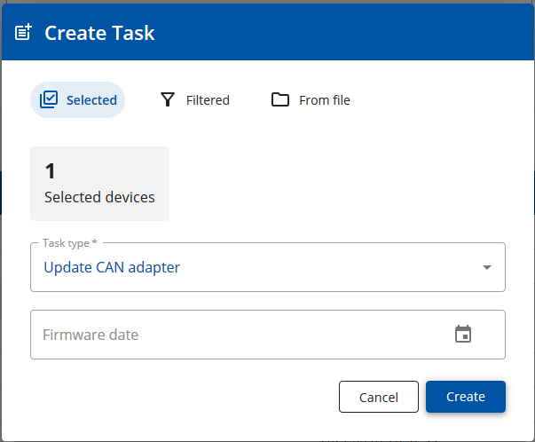
To update the software, first select the device check-box.

-
Then, click the “Select task” button and set the task type to “Update CAN adapter”.
-
The configured task can be seen in the main window. The update will start after the next scheduled connection to FOTA WEB (or after web_connect SMS command).

- When the update completes, the new software version can be seen in the details window.


CAN Adapter State Flags
SECURITY STATE FLAGS P4
| Byte | Bit | Value bitmasks | LVCAN + DTC | ALLCAN | CAN-CONTROL |
|---|---|---|---|---|---|
| 0 | 0 | 0x00 – CAN1 connected, currently no data is received; 0x01 – CAN1 connected, currently data is received; 0x02 – CAN1 not connected, needs connection; 0x03 – CAN1 not connected does not need connection | TRUE | TRUE | TRUE |
| 0 | 2 | 0x00 – CAN2 connected, currently no data is received; 0x01 – CAN2 connected, currently data is received; 0x02 – CAN2 not connected, needs connection; 0x03 – CAN2 not connected does not need connection | TRUE | TRUE | TRUE |
| 0 | 4 | 0x00 – CAN3 connected, currently no data is received; 0x01 – CAN3 connected, currently data is received; 0x02 – CAN3 not connected, needs connection; 0x03 – CAN3 not connected does not need connection | TRUE | ||
| 0 | 6 | RESERVED | |||
| 0 | 7 | RESERVED | |||
| 1 | 8 | 0x01 – ignition on | TRUE | TRUE | TRUE |
| 1 | 9 | 0x02 – key in ignition lock | TRUE | TRUE | |
| 1 | 10 | 0x04 – webasto | TRUE | ||
| 1 | 11 | 0x08 – engine is working | TRUE | TRUE | |
| 1 | 12 | 0x10 – standalone engine | TRUE | ||
| 1 | 13 | 0x20 – ready to drive | TRUE | TRUE | |
| 1 | 14 | 0x40 – engine is working on CNG | TRUE | TRUE | TRUE |
| 1 | 15 | 0x80 – work mode (0 – private, 1 – company) | TRUE | ||
| 2 | 16 | 0x01 – operator is present | TRUE | ||
| 2 | 17 | 0x02 – interlock active | TRUE | ||
| 2 | 18 | 0x04 – handbrake is active | TRUE | TRUE | |
| 2 | 19 | 0x08 – footbrake is active | TRUE | TRUE | |
| 2 | 20 | 0x10 – clutch is pushed | TRUE | ||
| 2 | 21 | 0x20 – status of the hazard warning lights switch active | TRUE | TRUE | |
| 2 | 22 | 0x40 – front left door opened | TRUE | TRUE | TRUE |
| 2 | 23 | 0x80 – front right door opened | TRUE | TRUE | TRUE |
| 3 | 24 | 0x01 – rear left door opened | TRUE | TRUE | TRUE |
| 3 | 25 | 0x02 – rear right door opened | TRUE | TRUE | TRUE |
| 3 | 26 | 0x04 – trunk door opened | TRUE | TRUE | TRUE |
| 3 | 27 | 0x08 – engine cover opened | TRUE | TRUE | TRUE |
| 3 | 28 | 0x10 – charging wire is plugged | TRUE | TRUE | TRUE |
| 3 | 29 | 0x20 – battery charging on | TRUE | TRUE | TRUE |
| 3 | 30 | 0x40 – electric engine is working | TRUE | TRUE | TRUE |
| 3 | 31 | 0x80 – car is closed with factory remote control | TRUE | TRUE | |
| 4 | 32 | 0x01 – car is closed | TRUE | TRUE | |
| 4 | 33 | 0x02 – factory installed alarm is active | TRUE | TRUE | |
| 4 | 34 | 0x04 – emulated alarm is active | TRUE | TRUE | |
| 4 | 35 | 0x08 – signal of closing with factory remote control was sent | TRUE | TRUE | |
| 4 | 36 | 0x10 – signal of opening with factory remote control was sent | TRUE | TRUE | |
| 4 | 37 | 0x20 – rearm signal was sent | TRUE | TRUE | |
| 4 | 38 | 0x40 – trunk was opened with remote control | TRUE | TRUE | |
| 4 | 39 | 0x80 – CAN module is in SLEEP mode | TRUE | TRUE | TRUE |
| 5 | 40 | 0x01 – signal of closing with factory remote control was sent 3 times | TRUE | ||
| 5 | 41 | 0x02 – parking is active | TRUE | TRUE | |
| 5 | 42 | 0x04 – reverse is active | TRUE | TRUE | |
| 5 | 43 | 0x08 – neutral is active | TRUE | TRUE | |
| 5 | 44 | 0x10 – drive is active | TRUE | TRUE | |
| 5 | 45 | 0x20 – engine lock active | TRUE | ||
| 5 | 46 | 0x40 – request to lock the engine (activation after attempt to restart the engine) | TRUE | ||
| 5 | 47 | 0x80 – factory armed (only 03.25.16.Rev.280, 03.25.16.Rev.290) | TRUE | ||
| 6 | 48 | 0x01 - roof opened | TRUE | TRUE | TRUE |
| 6 | 49 | 0x02 - engine working on dual fuel | TRUE | TRUE | TRUE |
| 6 | 50 | 0x04 - engine working on LPG | TRUE | TRUE | TRUE |
| 6 | 51 | RESERVED | |||
| 6 | 52 | RESERVED | |||
| 6 | 53 | RESERVED | |||
| 6 | 54 | RESERVED | |||
| 6 | 55 | RESERVED | |||
| 7 | 56 | RESERVED | |||
| 7 | 57 | RESERVED | |||
| 7 | 58 | 0x04 - front left window open (has never been in base; checked 04.02.00.Rev.01) | TRUE | ||
| 7 | 59 | 0x08 - front right window open (has never been in base; checked 04.02.00.Rev.01) | TRUE | ||
| 7 | 60 | 0x10 - rear left window open (has never been in base; checked 04.02.00.Rev.01) | TRUE | ||
| 7 | 61 | 0x20 - rear right window open (has never been in base; checked 04.02.00.Rev.01) | TRUE | ||
| 7 | 62 | RESERVED | |||
| 7 | 63 | RESERVED |