Difference between revisions of "Automotive Relay"
From Wiki Knowledge Base | Teltonika GPS
| (27 intermediate revisions by 2 users not shown) | |||
| Line 1: | Line 1: | ||
| + | [[File:Relay Photo.png|Frame|Relay|300px|right]] | ||
__TOC__ | __TOC__ | ||
=Introduction to the product= | =Introduction to the product= | ||
| − | + | The purpose of the relay is to automate the closing / opening of the electrical circuit when an electrical signal is applied. | |
| + | <br> | ||
| + | '''Relays are great in these use cases:''' | ||
| − | |||
* [[Anti-Theft_Solution_and_Stolen_Vehicle_Recovery|Anti-Theft Solution and Stolen Vehicle Recovery]] | * [[Anti-Theft_Solution_and_Stolen_Vehicle_Recovery|Anti-Theft Solution and Stolen Vehicle Recovery]] | ||
| − | * [ | + | * [[https://wiki.teltonika-gps.com/view/Secure_vehicle_disabling|Secure vehicle disabling]] |
| − | + | * Automated Drivers Time Tracking And Identification <br> | |
| − | + | ||
| + | |||
| + | |||
=Product Specification= | =Product Specification= | ||
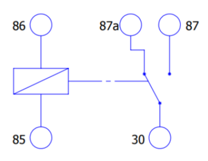
[[Image:Relay scheme.png|thumb|Relay schematic diagram|300px|right]] | [[Image:Relay scheme.png|thumb|Relay schematic diagram|300px|right]] | ||
| Line 52: | Line 56: | ||
| style="border: 1px solid white; border-bottom: 2px solid #E8E8E8; text-align: left; vertical-align: center; background: white;" |Weight | | style="border: 1px solid white; border-bottom: 2px solid #E8E8E8; text-align: left; vertical-align: center; background: white;" |Weight | ||
| style="border: 1px solid white; border-bottom: 2px solid #E8E8E8; text-align: left; vertical-align: center; background: white;" |40g | | style="border: 1px solid white; border-bottom: 2px solid #E8E8E8; text-align: left; vertical-align: center; background: white;" |40g | ||
| − | |||
| − | |||
| − | |||
|- | |- | ||
|} | |} | ||
| − | =Installation= | + | ==Installation== |
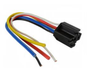
| + | [[Image:Relay wiring.png|thumb|Relay Wiring|300px|right]] | ||
{| class="wikitable" | {| class="wikitable" | ||
| Line 84: | Line 86: | ||
| style="border: 1px solid white; border-bottom: 2px solid #E8E8E8; text-align: left; vertical-align: center; background: white;" |87a | | style="border: 1px solid white; border-bottom: 2px solid #E8E8E8; text-align: left; vertical-align: center; background: white;" |87a | ||
| style="border: 1px solid white; border-bottom: 2px solid #E8E8E8; text-align: left; vertical-align: center; background: white;" |<span style="color:red"><b>Red</b></span> | | style="border: 1px solid white; border-bottom: 2px solid #E8E8E8; text-align: left; vertical-align: center; background: white;" |<span style="color:red"><b>Red</b></span> | ||
| − | | style="border: 1px solid white; border-bottom: 2px solid #E8E8E8; text-align: left; vertical-align: center; background: white;" |Normally Closed (NC) | + | | style="border: 1px solid white; border-bottom: 2px solid #E8E8E8; text-align: left; vertical-align: center; background: white;" |Normally Closed (NC) - not present on 4 pin relays |
| − | |||
| − | |||
| − | |||
| − | |||
| − | |||
| − | |||
| − | |||
| − | |||
| − | |||
| − | |||
| − | |||
| − | |||
| − | |||
| − | |||
| − | |||
| − | |||
| − | |||
| − | |||
| − | |||
| − | |||
| − | |||
| − | |||
|- | |- | ||
|} | |} | ||
| − | |||
[[Category:Accessories]] | [[Category:Accessories]] | ||
Revision as of 16:38, 14 October 2021
Main Page > Accessories > Automotive RelayIntroduction to the product
The purpose of the relay is to automate the closing / opening of the electrical circuit when an electrical signal is applied.
Relays are great in these use cases:
- Anti-Theft Solution and Stolen Vehicle Recovery
- [vehicle disabling]
- Automated Drivers Time Tracking And Identification
Product Specification
| Name | Value |
|---|---|
| Contact Rating | 30A/40A 14VDC |
| Coil Voltage | 12VDC |
| Coil Power | 1.8W |
| Release Voltage | ≥10% |
| Pickup Voltage | ≤70% |
| Insulation Resistance | 100Ω |
| Contact Resistance | 100Ω |
| Between open contact | 500VAC |
| Between coil & contact | 750VAC |
| Temperature Range | -55~+85℃ |
| Dimension | 25.0x27.4x28.4 |
| Weight | 40g |
Installation
| Relay PIN | Relay cable color | Connection |
|---|---|---|
| 30 | Blue | Common connection to NO & NC terminals |
| 85 | Black | Coil |
| 86 | White | Coil |
| 87 | Yellow | Normally Open (NO) |
| 87a | Red | Normally Closed (NC) - not present on 4 pin relays |


