Difference between revisions of "CONTINUOUS NETWORK CONNECTIVITY WITH AUTO TOP-UP FEATURE"
| Line 335: | Line 335: | ||
|} | |} | ||
| − | + | ==Demonstration in platform== | |
| − | |||
| − | |||
| − | + | TAVL: Open TAVL → select client → select Street Map → select device → choose the date from which to show the records → push advanced → push show button and then you will see in left down corner all information. | |
| − | + | [[File:TAVL_jamming.png|alt=|frameless|1153x1153px]] | |
| − | |||
| − | |||
| − | |||
| − | + | ||
| − | + | ||
| − | + | WIALON: Open WIALON → open messages → push unit ( select your device) → choose the date from which to show the records → select message (data messages) → push execute button and you will see all information. | |
| + | [[File:Wialonturbo.jpg|left|frameless|1155x1155px]] | ||
[[Category: Usage scenarios]] | [[Category: Usage scenarios]] | ||
Revision as of 10:02, 21 February 2023
Main Page > General Information > Usage scenarios > CONTINUOUS NETWORK CONNECTIVITY WITH AUTO TOP-UP FEATUREIntroduction
Many transport businesses are regulated by governments worldwide. For example, lorries must be equipped with digital tachographs so that the data is sent according to a schedule; E-TOLL, modern toll collection solutions, are governed and electronically charged. Reporting is being digitised and made mandatory at the government level. Given this, measures should be put in place to facilitate the ease of data transfer and ensure its stability.
Solution description
As most transport and logistics companies are controlled by public authorities, fleet owners are required to submit digital tachograph charts regularly based on strict rules. Failure to submit data on time will inevitably result in heavy fines. According to the UK government website GOV.UK, the maximum fine for failing to do so can reach up to £10,000 and as much as 2-year imprisonment!
In the case of E-TOLL, a GPS tracker sends information on the location of a vehicle, the data is processed in the payment collection system, and a local National Revenue Administration automatically taxes the vehicle or fleet owners respectively. For example, if the data is not submitted on time in Poland, a car owner has to pay a fine, which starts at €300 per violation, as stated on the Ministry of Finance website etoll.gov.pl.
But what happens if the data is used up or the mobile network SIM card expires? Of course, the tracking device will be disconnected from the GSM network and no data will be sent at all.
Fortunately, Teltonika Telematics has a practical solution to help corporate fleets avoid such needless fines and ensure that the SIM cards of GPS trackers are always connected to the GSM network.
Every single Teltonika vehicle GPS tracker has a placeholder for a plastic (regular) SIM card or a possibility to install an eSIM module. The SIM card or eSIM is part of the Teltonika Global Connectivity Solution and is used to connect to mobile networks, and the GPS device will be able to send and receive data to and from locations covered by the data plan.
For example, the Teltonika Global Plan currently allows you to prevent roaming costs in 110 countries around the world and uses the same amount of data anywhere. But the fact is, any data plan has a limited number of megabytes, and if they are used up, a GPS tracker loses an access to the mobile network.
How it works - to keep SIM cards up and running continuously without physical and manual interference, we offer the convenient and practical Auto Top-Up feature. As the name implies, when properly set up, this function automatically renews the same data plan under the same conditions when the remaining amount of data has been used up to a specified limit. Thanks to it, fleet managers and business owners will not run into trouble if a SIM card plan data is nearly used up, or expiration term is around the corner but a person in charge has missed all the notifications, off duty, or simply forgot to top up the plan timely.
With the SIM card management IoT Platform, you can set up specific SIM cards to be topped up, choose notification rules (via email or SMS) when 90% or any other percentage of data is used up, or inform a person in charge that the last top-up has been depleted and there are no more of them left. As a result, there is no point to monitor the amount of data or the expiry date anymore, as automatic top-ups reduce the need for manual maintenance of the SIM cards, and fleet GPS trackers will always remain connected to the GSM network with no service interruptions.
What you need for a solution?
- Any FMx device
- The GLOBAL CONNECTIVITY SOLUTION SIM card in order to get data to your server
- IoT Platform to manage SIM cards.
Installation
It’s important to hide the tracker, so it would not be a simple task for the thieves to find and unplug it. But also, please do not forget to follow mounting recommendations as well (using the FMB130 device as an example).
Although devices have high gain antennas it’s important to mount devices with stickers on top and in metal-free space. The device should be firmly fixed to the surface or cables. Please make sure, that device is not fixed to heat emitting or moving parts.
The main solution in this case is the automatic charging of traffic in the IoT platform. If the Truphone SIM card is not installed from the factory, then install it yourself.
Configuration
1. Prerequisites:
1.1. Read through First start guide
1.2. Understanding of possible Sleep modes.
1.3. Activate on the IoT Platform using the details provided by the sales manager.
2. CONTINUOUS NETWORK CONNECTIVITY WITH AUTO TOP-UP FEATURE configuration:
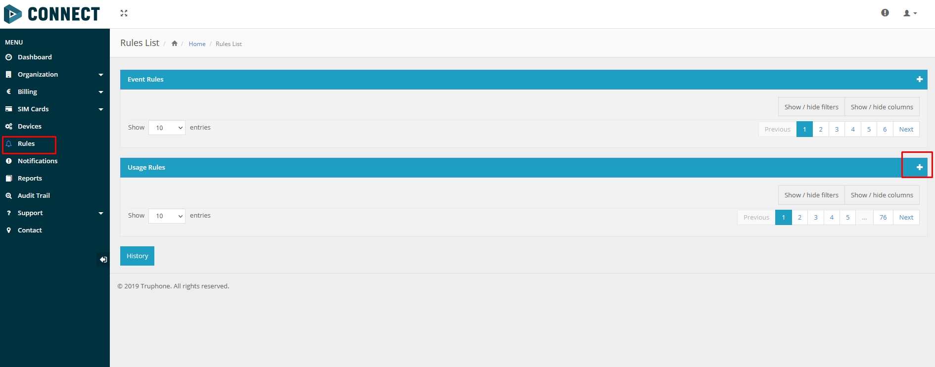
1. Navigate to the "Rules" menu and add a new Usage rule (Please refer to Picture 1)
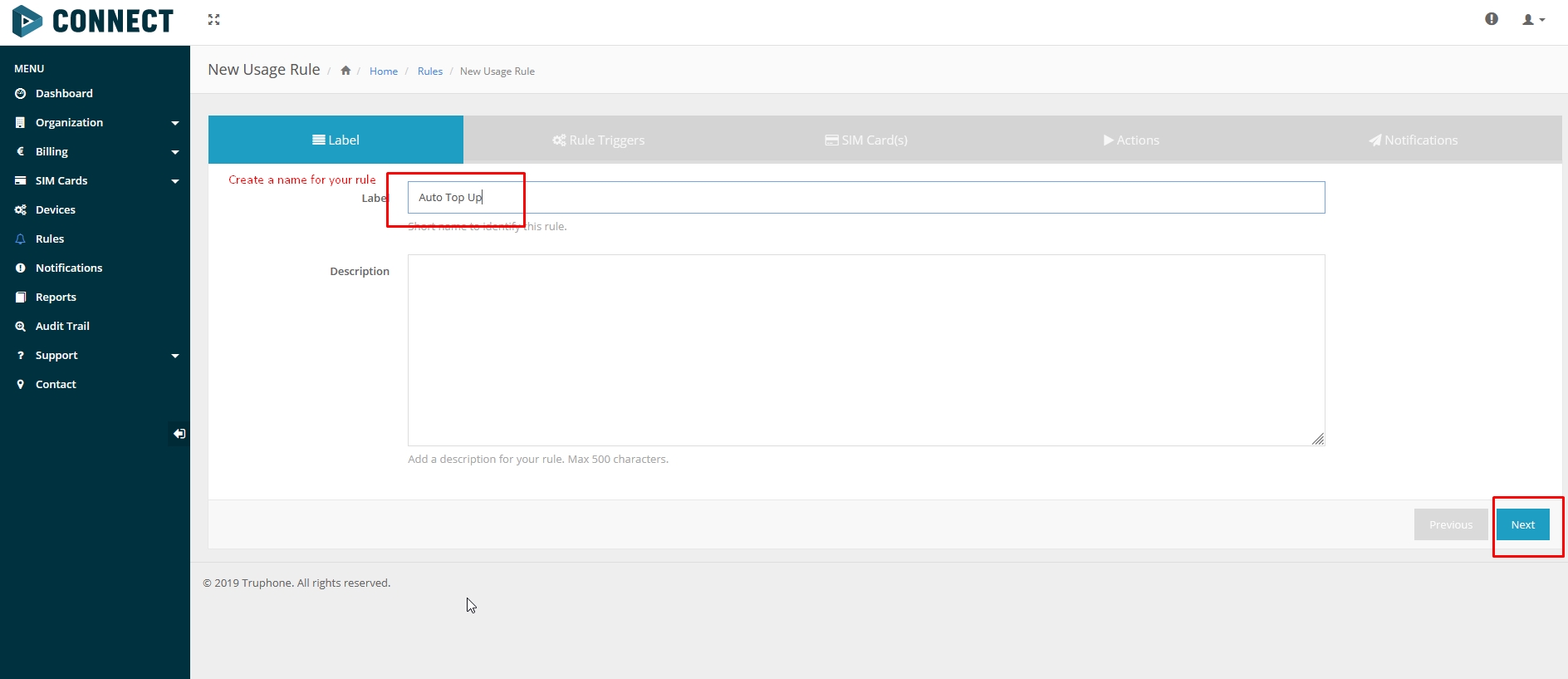
2. In the "Label" window enter Your preferred name. To distinguish different rules, in this example name is "Auto Top Up" (Please refer to Picture 2)
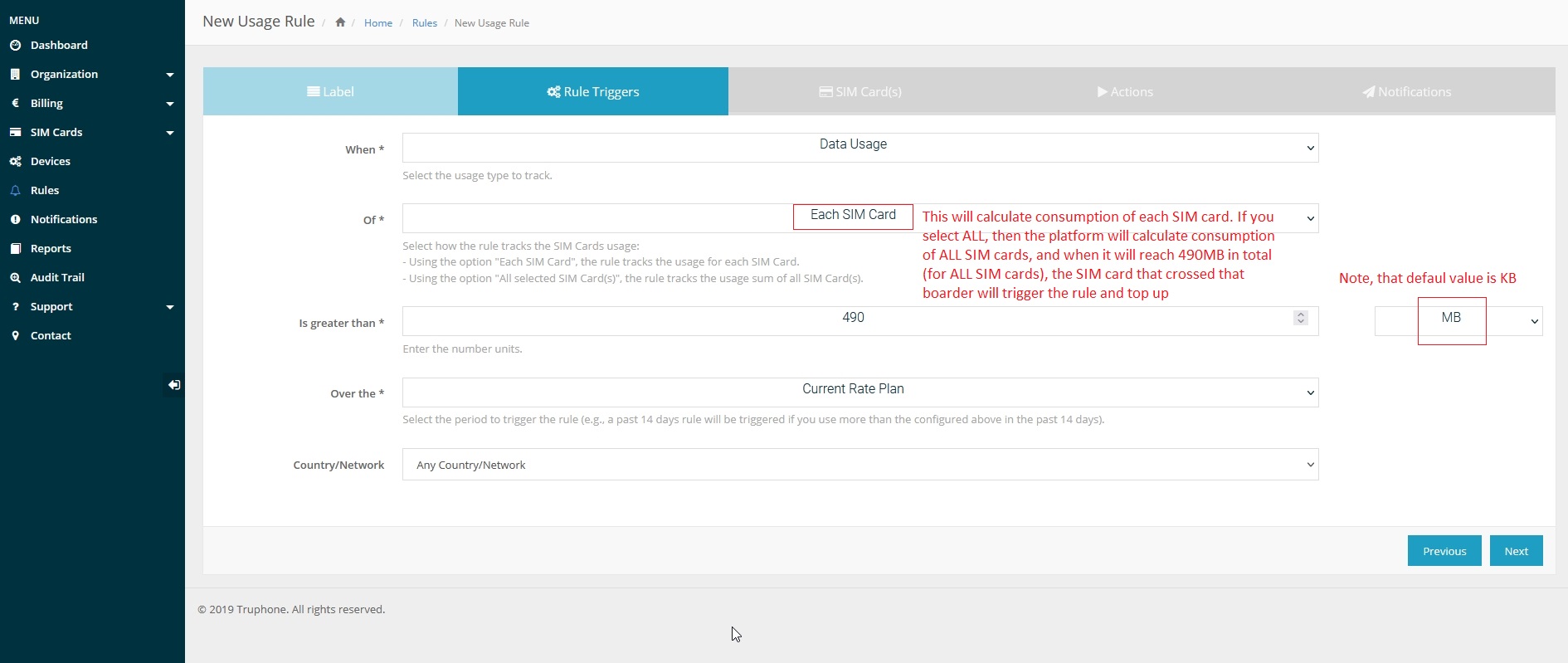
3. In the "Rule Triggers" select the following settings (Please refer to Picture 3):
- When — Data Usage.
- Of — Each SIM Card.
- Is greater than — In this example value is 490 MB, but it can be customized according to Your needs.
- Over the — Current Rate Plan
- Country/Network — Any Country/Network
4. In SIM Card(s) window select "All SIM Cards" (Please refer to Picture 4)

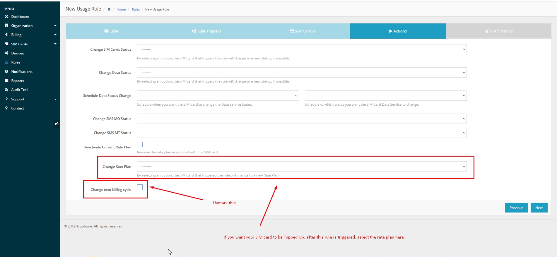
5. In the Actions window select the rate plan that will be applied to the SIM card and Uncheck "Change next billing cycle" (Please refer to Picture 5)
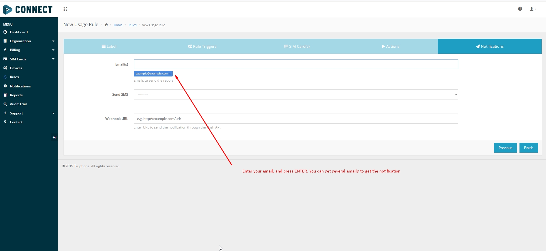
6. Select an email where the notification will be sent (Please refer to Picture 6)
Parsing information
1.Prerequisites:
1.1. Open TCP/UDP port
1.2. Read Java parser first start guide
2. Parsing example:
| Unparsed received data in hexadecimal stream |
|---|
| 000000000000008F080100000177B0A5F838000000000000000000004400280D0000001F09EF00F0001504B301B40051005200590098000B42307443
0F8244000011001812002D13FFE85400BE5500005A0000970000A800000AF10000601A53000000005703CB6B986400002E 97660000000069023B33856B000065B27B000000007D00000000BD00000000018400800000300000050100005C92 |
| AVL Data Packet Part | HEX Code Part |
|---|---|
| Zero Bytes | 00 00 00 00 |
| Data Field Length | 00 00 00 8F |
| Codec ID | 08 (Codec 8) |
| Number of Data 1 (Number of Total Records) | 01 |
| Timestamp | 00 00 01 77 B0 A5 F8 38 (Thursday, February 18, 2021 3:43:00 PM GMT+02:00) |
| Priority | 00 |
| Longitude | 00 00 00 00 |
| Latitude | 00 00 00 00 |
| Altitude | 00 44 |
| Angle | 00 28 |
| Satellites | 0D |
| Speed | 00 00 |
| Event IO ID | 00 |
| N of Total ID | 1F |
| N1 of One Byte IO | 09 |
| 1’st IO ID | EF (AVL ID: 239, Name: Ignition) |
| 1’st IO Value | 00 |
| 2’nd IO ID | F0 (AVL ID: 240, Name: Movement) |
| 2’nd IO Value | 00 |
| 3’rd IO ID | 15 (AVL ID: 21, Name: GSM Signal) |
| 3’rd IO Value | 04 |
| 4'th IO ID | B3 (AVL ID: 179, Name: Digital Output 1) |
| 4'th IO Value | 01 |
| 5'th IO ID | B4 (AVL ID: 180, Name: Digital Output 2) |
| 5'th IO Value | 00 |
| 6'th IO ID | 51 (AVL ID: 81, Name: Vehicle Speed) |
| 6'th IO Value | 00 |
| 7'th IO ID | 52 (AVL ID: 82, Name: Accelerator Pedal Position) |
| 7'th IO Value | 00 |
| 8'th IO ID | 59 (AVL ID: 89, Name: Fuel level) |
| 8'th IO Value | 00 |
| 9'th IO ID | 98 (AVL ID: 152, Name: Geofence zone 05) |
| 9'th IO Value | 00 |
| N2 of Two Byte IO | 0B |
| 1’st IO ID | 42 (AVL ID: 66, Name: External Voltage) |
| 1’st IO Value | 30 74 |
| 2’nd IO ID | 43 (AVL ID: 67, Name: Battery Voltage) |
| 2’nd IO Value | 0F 82 |
| 3’rd IO ID | 44 (AVL ID: 68, Name: Battery Current) |
| 3’rd IO Value | 00 00 |
| 4'th IO ID | 11 (AVL ID: 17, Name: Axis X) |
| 4'th IO Value | 00 18 |
| 5'th IO ID | 12 (AVL ID: 18,Name: Axis Y) |
| 5'th IO Value | 0F 8A |
| 6'th IO ID | 13 (AVL ID: 19, Name: Axis Z) |
| 6'th IO Value | FF E8 |
| 7'th IO ID | 54 (AVL ID: 84,Name: Fuel level) |
| 7'th IO Value | 00 BE |
| 8'th IO ID | 55 (AVL ID:85, Name: Engine RPM) |
| 8’th IO Value | 00 00 |
| 9'th IO ID | 5A (AVL ID:90, Name: Door Status) |
| 9’th IO Value | 00 00 |
| 10'th IO ID | 97 (AVL ID:151, Name: Battery Temperature) |
| 10'th IO Value | 00 00 |
| 11'th IO ID | A8 (AVL ID: 168, Battery Voltage) |
| 11'th IO Value | 00 00 |
| N4 of Four Byte IO | 0A |
| 1'st IO ID | F1 (AVL ID: 241, Name: Active GSM Operator) |
| 1’st IO Value | 00 00 60 1A |
| 2’nd IO ID | 53 (AVL ID: 83, Name: Fuel Consumed) |
| 2’nd IO Value | 00 00 00 00 |
| 3’rd IO ID | 57 (AVL ID: 87, Name: Total Mileage) |
| 3’rd IO Value | 03 CB 6B 98 |
| 4’th IO ID | 64 (AVL ID: 100, Name: Program Number) |
| 4’th IO Value | 00 00 2E 97 |
| 5’th IO ID | 66 (AVL ID: 102, Name: Engine Worktime) |
| 5’th IO Value | 00 00 00 00 |
| 6’th IO ID | 69 (AVL ID: 105, Name: Total Mileage (counted)) |
| 6’th IO Value | 02 3B 33 85 |
| 7’th IO ID | 6B (AVL ID: 107, Name: Fuel Consumed(counted)) |
| 7’th IO Value | 00 00 65 B2 |
| 8’th IO ID | 7B (AVL ID: 123, Name: Control State Flags) |
| 8’th IO Value | 00 00 00 00 |
| 9’th IO ID | 7D (AVL ID: 125, Name: Harvesting Time) |
| 9’th IO Value | 00 00 00 00 |
| 10’th IO ID | BD (AVL ID: 189, Name: Cruise Time) |
| 10’th IO Value | 00 00 00 00 |
| N8 of Eight Byte IO | 01 |
| 1'st IO ID | 84 (AVL ID: 132, Name: Security State Flags) |
| 1’st IO Value | 00 80 00 00 30 00 00 05 |
| Number of Data 2 (Number of Total Records) | 01 |
| CRC-16 | 00 00 5C 92 |
Demonstration in platform
TAVL: Open TAVL → select client → select Street Map → select device → choose the date from which to show the records → push advanced → push show button and then you will see in left down corner all information.

WIALON: Open WIALON → open messages → push unit ( select your device) → choose the date from which to show the records → select message (data messages) → push execute button and you will see all information.


