|
|
| Line 1: |
Line 1: |
| − | | + | {{Template:Accessories|model=FMB001 |
| − | | + | |Teltonika DualCam = |
| − | {| class="nd-othertables_2" style="border-style: solid; border-width: 0px" | + | |ADAS = |
| − | |+
| + | |LV-CAN200 = |
| − | |-
| + | |ALL-CAN300 = |
| − | | style="text-align: left;" |[[Image:Bw_nb.png|50px]]
| + | |CAN-CONTROL = |
| − | | style="text-align: left;" |Please order accessories separately as they are not included into device package.
| + | |Analog Fuel Sensor = |
| − | |-
| + | |1-Wire Temperature Sensor = |
| − | |}
| + | |1-Wire TTJ Temperature Sensor = |
| − | | + | |1-Wire iButton Reader = |
| − | {| class="nd-othertables_2" | + | |1-Wire RFID Reader = |
| − | |+
| + | }} |
| − | ! style="width: 300px; color: white;" |Accessory and its description
| + | [[Category:FMB001 Manual]] |
| − | ! style="width: 500px; color: white;" |Accessory connection schematic
| |
| − | |-
| |
| − | | |
| − | ! style="text-align: left; vertical-align: top;" |Fuel tank sensors
| |
| − | ! style="text-align: center; vertical-align: top;" |Fuel sensor connection to {{{model|FMB1YX}}}
| |
| − | |-
| |
| − | | style="text-align: left; vertical-align: top;" |A fuel tank level sensor that indicates the approximate fuel level on the driver's indicator panel exists in most cars. If the sensor returns an analog signal proportional to fuel level it can be connected to {{{model|FMB1YX}}} Analog input. After connection to the tank fuel level sensor, a calibration is needed because most fuel tank sensors are not linear. Calibration is performed by measuring voltage values resulting from the volume of fuel in the tank.
| |
| − | | style="text-align: left; vertical-align: top;" |[[Image:Sch_fmb1yx_lls.png|250px|center]] | |
| − | |- | |
| − | ! style="text-align: left; vertical-align: top;" |Alarm buttons, door sensors etc.
| |
| − | ! style="text-align: center; vertical-align: top;" |Panic button connection to {{{model|FMB1YX}}}
| |
| − | |- | |
| − | | style="text-align: left; vertical-align: top;" |Alarm buttons, door sensors, ignition, etc. have two output states: high or low. {{{model|FMB1YX}}} Digital inputs are used to detect these states.
| |
| − | | style="text-align: left; vertical-align: top;" |[[Image:Sch_fmb1yx_panic.png|400px|center]]
| |
| − | |- | |
| − | ! style="text-align: left; vertical-align: top;" |Relays
| |
| − | ! style="text-align: center; vertical-align: top;" |Inverting relay connection to {{{model|FMB1YX}}}
| |
| − | |- | |
| − | | style="text-align: left; vertical-align: top;" |In cases when the sensor output signal is negative, an additional relay has to be installed to convert the negative signal to positive.
| |
| − | | style="text-align: left; vertical-align: top;" |[[Image:Sch_fmb1yx_inv_relay.png|400px|center]] | |
| − | |- | |
| − | ! style="text-align: left; vertical-align: top;" |Immobilizer relay
| |
| − | ! style="text-align: center; vertical-align: top;" |Immobilizer relay connection to {{{model|FMB1YX}}} output
| |
| − | |- | |
| − | | style="text-align: left; vertical-align: top;" |When connected as shown on the right hand side, {{{model|FMB1YX}}} disables engine starter when output is ON.
| |
| − | | style="text-align: left; vertical-align: top;" |[[Image:Sch_fmb1yx_imb_relay.png|400px|center]]
| |
| − | |-
| |
| − | ! style="text-align: left; vertical-align: top;" |Automotive relay
| |
| − | ! style="text-align: center; vertical-align: top;" |Automotive relay pinout
| |
| − | |-
| |
| − | |-
| |
| − | | style="text-align: left; vertical-align: top;" |An ordinary automotive relay is used to invert input signal or to immobilize engine starter. Note that relays can be 12 V or 24 V capable.<br />[[Image:Pic_relay.png|150px|center]]
| |
| − | | style="text-align: left; vertical-align: top;" |[[Image:Sch_ord_relay.png|250px|center]]
| |
| − | |-
| |
| − | ! style="text-align: left; vertical-align: top;" |{{{oneWire|1-Wire devices}}}
| |
| − | ! style="text-align: center; vertical-align: top;" |{{{oneWire|Digital thermometer DS1820 and TTJ100 connection to {{{model|FMB1YX}}} }}}
| |
| − | |- | |
| − | | rowspan="5" style="text-align: left; vertical-align: top;" |{{{oneWire|One of the implemented features on {{{model|FMB1YX}}} is 1-Wire® data protocol, which enables connection to devices such as thermometer (DS1820, DS18S20 and DS18B20) and I-Button DS1990A. }}}
| |
| − | | |
| − | Accessories that use 1-Wire Power and 1-Wire Data connections are not compatible with the FMB140, because it lacks a 1-Wire Power pin.
| |
| − | | style="text-align: left; vertical-align: top;" |{{{oneWire| {{{pic_ds1820|[[Image:Sch_fmb120_ds1820.png|400px|center]]}}} }}}
| |
| − | |-
| |
| − | ! style="text-align: center; vertical-align: top;" |{{{oneWire| I-Button DS1990A connection to {{{model|FMB1YX}}} }}}
| |
| − | |-
| |
| − | | style="text-align: left; vertical-align: top;" |{{{oneWire| [[Image:Sch_fmb1yx_ibutton.png|400px|center]] }}}
| |
| − | |-
| |
| − | |}
| |
| − | | |
| − | [[Category:FMB140 Manual]] | |
EYE Beacon
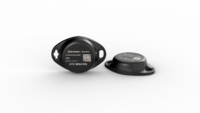
BLE Beacon for traceability use cases, delivery tracking, monitoring of various movable objects in logistics (trailers, containers), agriculture (tractor attachments), and constructions (tools and inventory).
EYE Sensor
Sensors data makes it especially suitable for cold chain refrigerator use cases. The built-in accelerometer can detect item movement or fall events. Magnet detection can be used for wireless open/close detection and notifications such as trailer door events, etc.
Teltonika ADAS
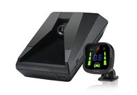
It is ideal to avoid potential accidents as its camera detects vehicles, pedestrians, bicycles, motorcycles, and lane markings on the roads. ADAS notifies the driver with sound and visual warnings of various events. Safety features are designed to avoid collisions and traffic accidents by offering technologies that alert drivers, fleet managers, and dispatchers to potential collisions or common mistakes on the road by tracking and monitoring events in real-time.
ECAN01
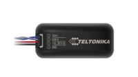
Contactless connection to the CAN bus of the vehicle! It reads can bus data through the isolation of wires without damaging them and forwards signals to tracking device.


